
Section IV. EXHAUST SYSTEM
76. General
The engine exhaust system consists of two air cooled manifolds mounted on the left side of the cylinder head below
the water manifold. The exhaust pipe extends through the hood of the engine which provides for the mounting of a one-
piece muffler. Water is prevented from entering the exhaust system and cylinder head by a weighted cap, secured to the
top of the muffler.
77. Muffler Assembly
a. Removal. Remove the muffler in reverse of instructions on figure 7.
b. Cleaning and Inspection. Clean and inspect the muffler and clamps. Replace a defective muffler and mounting
clamps.
c. Installation. Install the muffler as instructed on figure 7.
78. Exhaust Pipes and Manifold
a. Removal.
(1) Remove the muffler assembly (par. 77).
(2) Remove the engine housing door supports (par. 97).
(3) Remove the exhaust pipe and manifolds as instructed on figure 28.
b. Cleaning and Inspection. Clean and inspect the exhaust pipes and manifolds for damage. Replace damaged parts.
c. Installation.
(1) Install the exhaust pipe and manifolds in reverse of instructions on figure 28.
(2) Install the engine housing door supports (par. 97).
(3) Install the muffler assembly (par. 77).
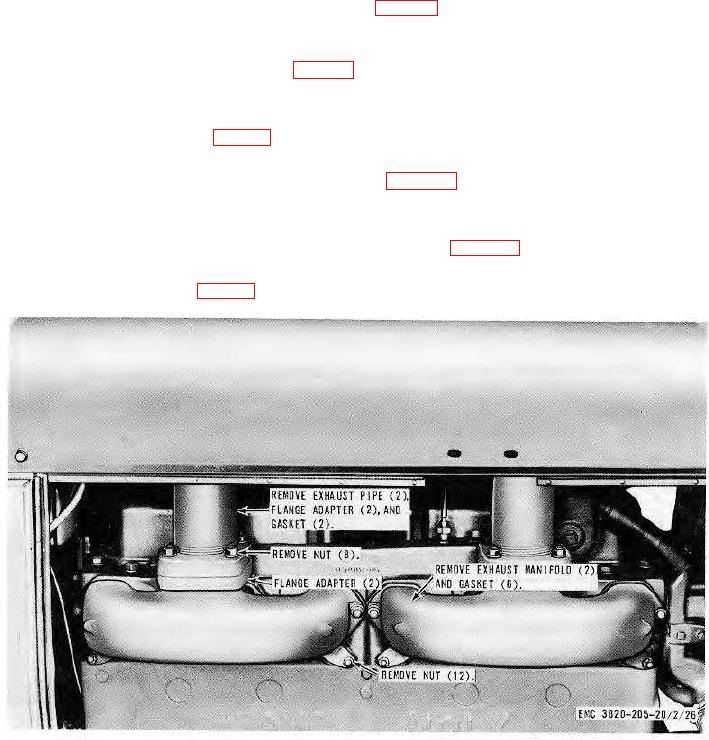
Figure 28. Exhaust pipe and manifolds, removal and installation.
AGO 8156A
44