
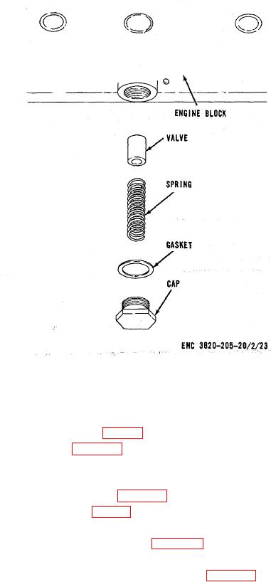
Figure 26. Oil cooler bypass valve, removal and installation.
73. Oil Cooler
a. Removal.
(1) Remove the oil filters and mounting bracket (par. 71).
(2) Remove the oil cooler as instructed on figure 27.
b. Cleaning and Inspection. Clean and inspect the oil cooler. Replace if necessary.
c. Installation.
(1) Install the oil cooler in reverse of instructions on figure 27.
(2) Install the mounting bracket and oil filters (par. 71).
74. Crankcase Breather
a. Removal. Remove the crankcase breather as instructed on figure 27.
b. Cleaning and Inspection. Clean and inspect the crankcase breather. Replace if necessary.
c. Installation. Install the crankcase breather in reverse of instructions on figure 27.
75. Oil Lines and Fittings
a. Removal. Remove the oil lines and fittings (pars. 71 and 74).
b. Cleaning and Inspection. Clean and inspect the oil lines and fittings. Replace as necessary.
c. Installation. Install the oil lines and fittings (pars. 71 and 74).
AGO 8156A
42