
(5)
Connect the fuel line to the fuel tank (par. 68).
Caution: If fuel line connector screws (fig. 5) are loosened when connecting the line assemblies,
new washers must be installed and the screws torqued to the proper tension of 420 inch-pounds.
Overtorquing screws will crush the copper gaskets allowing the screws to bottom.
Section III. ENGINE LUBRICATION SYSTEM
70. General
The engine lubrication system is a pressurized-type. A gear-type oil pump attached to the bottom of the engine
crankcase provides oil under pressure from the engine oil pan to the moving parts of the engine. The oil cooler bypass
valve allows the engine oil to continue to flow through the lubrication system should the oil cooler become clogged. The
engine oil is filtered by three oil filters.
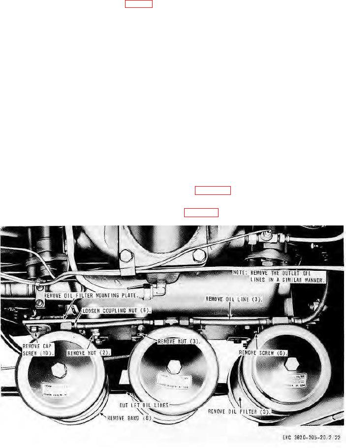
71. Oil Filters and Mounting Bracket
a. Removal. Remove the oil filters and mounting bracket as instructed on figure 25.
b. Cleaning and Inspection. Clean and inspect the oil filters and bracket. Replace all damaged parts.
c. Installation. Install the oil filters and mounting bracket in reverse of instruction on figure 25.
72. Oil Cooler Bypass Valve
a. Removal. Remove the oil cooler bypass valve as illustrated on figure 26.
b. Cleaning and Inspection. Clean and inspect all parts. Replace all worn or damaged parts as necessary.
c. Installation. Install the oil cooler bypass valve illustrated on figure 26.
AGO 8156A
41