
(2) Install the clearance marker light (par. 125).
(3) Install the fuel tank cap and strainer (TM 5-3820-205-10/2).
(4) Install the fuel gage (par. 58).
69. Fuel Line and Fittings
a. Removal.
(1) Disconnect the fuel lines from the fuel tank (par. 68).
(2) Disconnect the fuel lines from the fuel primer (par. 59).
(3) Disconnect the fuel lines from the fuel filter (par. 67).
(4) Disconnect the fuel lines from the fuel injectors (par. 65).
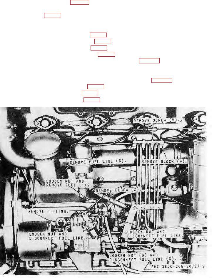
(5) Disconnect the fuel lines from the fuel injector pump as instructed on figure 24.
b. Cleaning, Inspection, and Repair. Clean and inspect all parts. Repair or replace damaged parts.
c. Installation.
(1) Connect the fuel lines to the fuel injector pump in reverse of instructions on figure 24.
(2) Connect the fuel lines to the fuel injectors (par. 65).
(3) Connect the fuel lines to the fuel filters (par. 67).
(4) Connect the fuel lines to the fuel primer (par. 59).
Figure 24. Fuel injector pump fuel lines, removal and installation.
AGO 8156A
40