
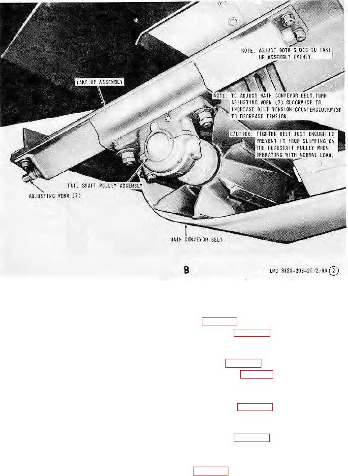
B-Main conveyor halt tension adjustment
Figure 85-Continued.
162. Impact Roller Assemblies
a. Removal. Remove the impact roller assemblies as instructed on figure 91.
b. Disassembly. Disassemble the impact roller assemblies as illustrated on figure 92.
c. Cleaning, Inspection, and Repair. Clean and inspect all parts for damage or defects. Repair or replace as
necessary.
d. Reassembly. Reassemble the impact roller assemblies as illustrated on figure 92.
e. Installation. Install the impact roller assemblies in reverse of instructions on figure 91.
163. Troughing Roller Assemblies
a. Removal. Remove throughing roller assemblies as instructed on figure 93.
b. Disassembly. Disassemble the troughing roller assemblies as illustrated on figure 94.
c. Cleaning, Inspection, and Repair. Clean and inspect all parts. Repair or replace defective or damaged parts as
necessary.
d. Reassembly. Reassemble the troughing roller assemblies as illustrated on figure 94.
e. Installation. Install the troughing roller assemblies in reverse of instructions on figure 93.
164. Return Roller Assembly
a. Removal. Remove the return roller assembly as instructed on figure 95.
b. Disassembly. Disassemble the return roller assembly as illustrated on figure 96.
AGO 8166A
110