
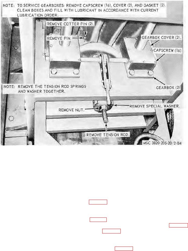
Figure 84. Tension spring and gear box covers, removal and installation.
Section VII. MAIN DISCHARGE CONVEYOR ASSEMBLY
157. General
The main discharge conveyor assembly receives the crusher rock from the crusher jaws, and may receive the material
from the diverter box for conveying out the rear of the jaw crusher. The main discharge conveyor consists of a conveyor
belt, an electric motor, motor drive belts, reducer gears, drive pulleys, head and tail scraper assemblies, impact troughing
and return rollers, head and tail shaft assemblies, and conveyor frame.
158. Main Discharge Conveyor Belt Adjustment
Adjust the main discharge conveyor belt as instructed on figure 85.
159. Main Discharge Conveyor Drive Gear Reducer and Sheave Assembly
a. Removal.
(1) Remove the main discharge conveyor drive belts (par. 129).
(2) Remove the main discharge conveyor drive gear reducer and sheave assembly as instructed on figure 86.
(3) Remove drive sheave from gear reducer as instructed on figure 86.
b. Cleaning and Inspection. Clean and inspect all parts. Replace a damaged or defective part.
c. Installation.
(1) Install drive sheave on gear reducer in reverse of instructions on figure 86.
AGO 8156A
108