
Figure 17. Fuel injection pump and governor assembly, exploded view.
gently, sliding the cam out of its
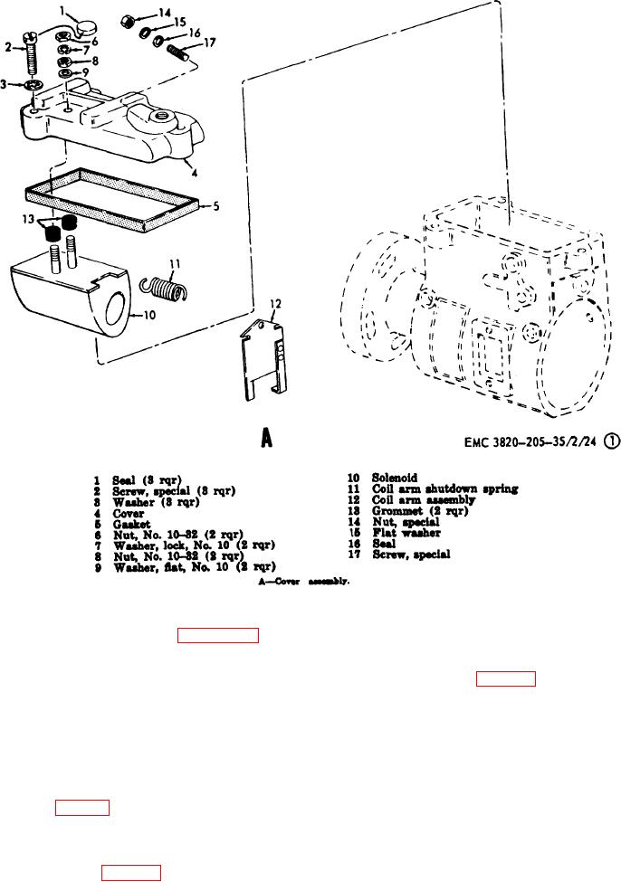
Disassembly.
Refer to figure 17 and
b.
groove and off the throttle shaft. The
disassemble the fuel injection pump and governor
end plate and hydraulic head
assembly.
assemblies (fig. 17D and E) are
Caution: When disassembling the
removed from the housing as a unit.
fuel injection pump and governor
66.
Fuel Injection Pump and Governor Assembly
assembly, keep all parts in a clean
Cleaning, Inspection, and Repair
pan containing clean fuel oil to keep
dust and abrasive material off of the
Cleaning. Clean all parts, except seals,
a.
accurately finished parts.
gaskets and preformed packing with a lint-free cloth
dampened in an approved cleaning solvent.
Note. When removing the shutoff
b.
Inspection and Repair.
cam (8, fig. 17B) rotate the lever
assembly (9) to the full shutoff
(1)
Inspect all packings, seals, and
position (shutoff cam horizontal).
gaskets for distortion, and breakage.
Place a suitable tool between the
Carefully
housing (32, fig. 17C) and the
governor hook assembly (7) and pry
AGO 3456A
43