
1
Key, 5/16 x 5/16 x 2 3/4 in.
18
Screw, No. 12-28 x 3/8 in. (3 rqr)
2
Setscrew, 1/8-32 x 1/4 in.
19
Dust shield
3
Oil slinger
20
Screw, cap, 5/16-18 x 2 in. (2 rqr)
4
Lubrication fitting
21
Washer, special (2 rqr)
5
Pipe plug
22
Screw, cap, 3/8-16 x 3 1/2 in. (4 rqr)
6
Nut, 5/16-18 (2 rqr)
23
Bearing support
7
Screw, cap, 5/16-18 x 2 in. (2 rqr)
24
Screw, No. 12-28 x 3/8 in. (3 rqr)
8
Clamp (2 rqr)
25
Dust shield
9
Fan
26
Rotor
10
Key, woodruff, No. 9
27
Bearing
11
Lubrication fitting
28
Gasket
12
Pipe, special
29
Retainer
13
Pipe, special
30
Bearing
14
Screw, cap, 3/8-16 x 4 in. (4 rqr)
31
Gasket
15
Screw, cap, 5/16 x 2 in. (2 rqr)
32
Retainer
16
Washer, special (2 rqr)
33
Lifting eye
17
Drive end bearing support
34
Frame and field assembly
Figure 36-Continued.
Section II. HOPPER ASSEMBLY
120. General
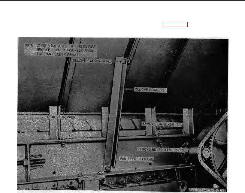
121. Hopper Assembly Removal
The hopper assembly is a welded construction of
Refer to figure 37 and remove the hopper
plate steel, angle braces, and mounting brackets. It is
assembly from the unit.
the receiving hopper for the rock that is to be crushed.
Figure 37. Hopper assembly, removal and installation.
75 AGO 8456A