TM 5-3820-233-12/1
(3) Walkway and hopper.
(a) Removal.
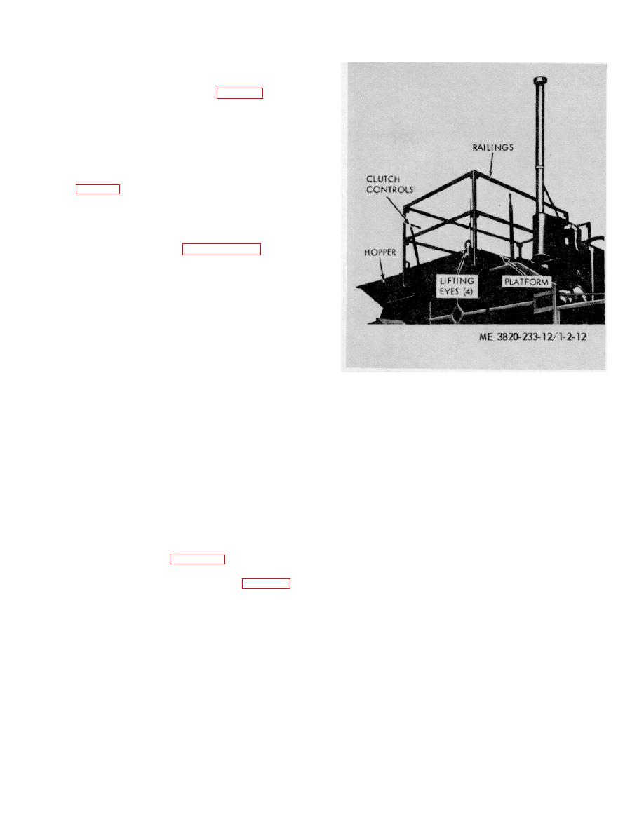
1. Remove clutch controls (fig. 2-12).
2. Remove railings and ladder.
3. Remove screws (8) attaching hopper and
platform to crusher.
4. Using a suitable lifting device remove
hopper and platform.
(b) Installation.
1. Lift hopper and platform into position on
crusher (fig. 2-12) and secure with attaching hardware.
2. Install upper ladder.
3. Connect clutch controls.
4. Install railings and post on platform.
2-6. Reinstallation After Movement
Follow the steps outlined in paragraph 2-2 for rein-
stallation instructions.
Figure 2-12. Walkway, removal and installations.
Section III. CONTROLS AND INSTRUMENTS
oil pressure gage to operate is a danger signal. Stop the
2-7. General
engine immediately and check the cause.
This section describes, locates, illustrates, and furnishes
e. Engine Oil Pressure Warning Lights. The engine
the operator, crew, or organizational maintenance
oil pressure warning light is located on right side of the
personnel sufficient information about the various
power take off end of the engine. When oil pressure is
controls and instruments for proper operation of the
below the operating minimum it will glow red. Replace a
crushing and screening unit.
defective light bulb or a defective fuse.
f. Water Temperature Gage. The water temperature
2-8. Controls and Instruments
gage is located to the left of the oil pressure gage. This
a. General. The purpose of the controls and
gage registers the temperature of liquid in the cooling
instruments and the normal and maximum reading of the
system and should show a gradual increase in
instruments are illustrated in figure 2-13.
temperature during engine warm up, to a normal
b. Tachometer. The tachometer is located above the
operating temperature of 160 to 185 F.
power take-off on the rear of the engine (fig. 2-13). It
g. Water Temperature Warning Lights. This light is
registers engine revolutions per minute. Recommended
located below the oil pressure warning light. The light
revolutions per minute is 1800 under load.
will glow red when water temperature is above the safe
c. Battery Charge Gage. The battery charge gage is
operation maximum. Replace a defective light bulb or a
located on the left hand upper corner on the rear of the
defective fuse.
engine. This instrument indicates the condition of the
h. Engine Clutch Lever. The engine clutch lever is
batteries when the engine is running.
located in front of the power take off, with a remote
d. Oil Pressure Gage. The oil pressure gage is
linkage to the plant clutch controls on the walkway.
located on rear of engine upper left hand corner. This
i. Starter Button. The starter button is located to the
instrument indicates the engine lubricating oil pressure.
right of the throttle control.
Normal oil pressure at operating temperature and speed
j. Throttle. The throttle is located to the right of the
is 38-60 pounds per square inch. With a cold engine, the
pressure may exceed this. This gage should show
pressure as soon as the engine is started. Failure of the
2-15


