TM 5-3820-233-35/1
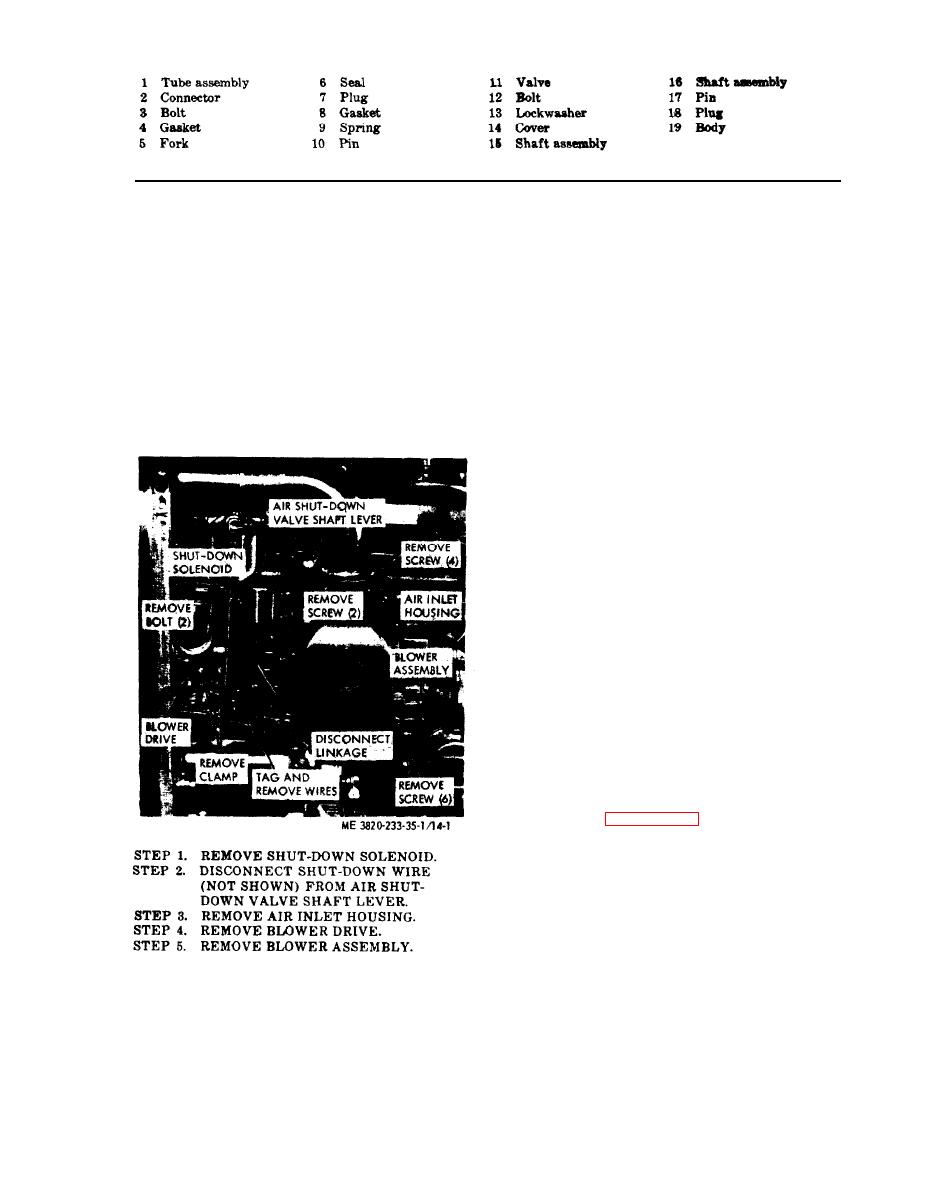
Figure 13 --Continued.
(7) Inspect the serrations in the blower
cloth. Replace excessively scored or burred
timing gears for wear and peening. Inspect
rotors.
gear teeth for wear, chipping, or other dam-
(4) Inspect rotor shaft serrations for
age. Backlash between gear teeth should not
wear, burrs, or peening. Replace defective
exceed 0.004 inch. Replace defective or dam-
rotor.
(5) Inspect the inside surfaces of the
aged timing gears as a set.
blower housing for burrs or scoring. Clean
(8) Inspect blower drive shaft serrations
up slightly scored or burred areas with emery
for wear or other damage. Replace a dam-
cloth.
aged or bent shaft.
(6) Inspect inside face of each end plate.
(9) Inspect the serrations inside the ro-
If the finished face is slightly scored or
tor drive hub for wear or other damage. Re-
burred, clean with emery cloth.
place a defective drive hub.
(10) Inspect the blower drive coupling
springs and cam for wear and other damage.
Replace defective parts.
(11) Inspect the thrust washers. Replace
worn or scored washers.
(12) Inspect bearings for binding, wear,
or scoring. Replace a defective bearing.
(13) Inspect the blower drive coupling
support, cam, spring seats, and spring packs
for wear or other damage. Replace any de-
fective parts.
(14) Inspect blower drive gear teeth for
chipping, wear, or scoring. Replace a defec-
tive gear.
(15) Replace worn or excessively dam-
aged air inlet housing, blower, and blower
drive parts.
c. Reassembly
(1) Reassemble the blower assembly in
the reverse of the numerical sequence as
illustrated on figure 14-4.
(a) Press oil seal (44) into the end
plate (37). Position the oil seal approxi-
mately .005 inch below the finished face of
the end plate. Install the remaining oil seals
in the end plates in the same manner.
(b) The dowel pins located on end
plates (31 and 46), must project. .380 inch
from the flat inner face and .270 inch from
the outer face of the end plates.
removal and installation.
3-17


