TM 5-3820-233-35/1
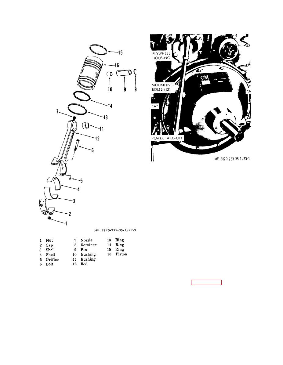
STEP 1. ATTACH A SUITABLE LIFTING TO
POWER TAKE-OFF ASSEMBLY.
STEP 2. ENGAGE THE CLUTCH.
STEP 3. REMOVE POWER TAKE-OFF MOUNT-
ING BOLTS.
STEP 4. INSTALL TWO OF THE MOUNTING
BOLTS IN HOLES "A", AND PUSH
ASSEMBLY FROM FLYWHEEL
HOUSING.
STEP 5. PULL POWER TAKE-OFF STRAIGHT
BACK FROM ENGINE.
(2) Inspect bearings for scoring, pitting,
and wear. Replace a defective bearing.
(3) Inspect the fan for visable damage.
Replace a defective fan.
(4) Inspect all parts for cracks, breaks,
and other damage. Repair or replace defective
parts.
Figure 22-2. Connecing rod and piston, exploded
d. Reassembly and Installation
view.
(1) Refer to figures 26-1 and 26-2, and
(4) Refer to figures 26-1 and 26-2 and
reassemble and install the pulley and hub as-
remove and disassemble the fan pulley and
sembly.
hub assembly.
(2) Torque the bearing retainer bolt
c. Cleaning, Inspection, and Repair
(11) to 83-93 foot-pound.
(1) Clean all parts with an approved
(3) Install radiator inlet hose.
cleaning solvent and dry thoroughly.
3-38


