
TM 5-3820-233-35/2
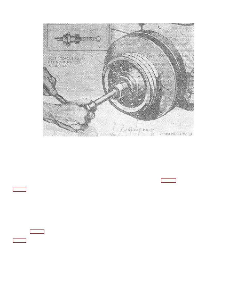
STEP 1. REMOVE CRANKSHAFT PULLEY.
Figure 28-1 (1). Crankshaft pulley and front cover, removal and installation.
(7) Inspect oil pump drive gear and
(2) Perform a magnetic inspection on the
crankshaft timing gear for chipped or cracked teeth.
crankshaft for cracks, breaks, or indications of fatigue.
Replace a defective gear.
Replace the crankshaft if any of the above mentioned
conditions exist.
(8) Measure
journal-to-bearing
shell
tolerance. Refer to table 1 for allowable tolerances.
(3) Measure the main bearing and connecting
Regrind or replace crankshaft as necessary-.
rod journals for wear and out of roundness. Refer to
Caution:
(4) Inspect the thrust washers for wear or
Crankshaft grinding operations must
roughness. Measure washer thickness. Refer to table I
for correct dimensions and tolerance data. Replace
be performed by an adequately
defective washers.
equipped shop and fully trained
personnel.
(5) Inspect main bearings for wear,
roughness., and overheating.
Replace defective
Note.
When a new or reground crankshaft
(6) Check runout of crankshaft journals.
is installed install all new main and
Refer to table 1 for correct tolerance and clearance
connecting rod bearing shells.
data. If the runout limit is greater than the data given in
3-45
