
TM 5-3820-233-35/2
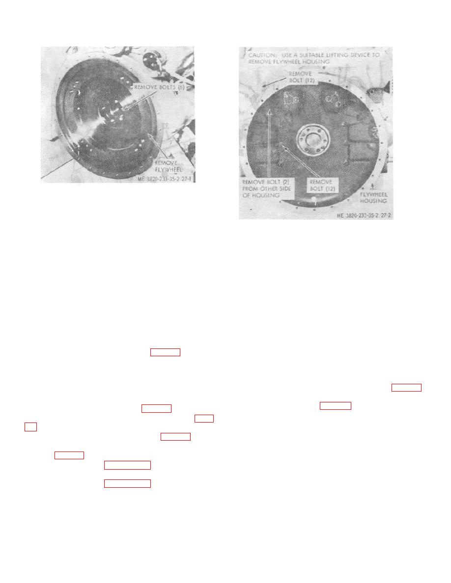
Figure 27-1. Flywheel, removal and installation.
(4) Install hoods, side panels, and tie cods
(Operator's Manual).
Figure 27-2. Flywheel housing, removal and
(5) Install the muffler and air cleaner
installation.
Operator's Manual.
c. Disassembly.
Disassemble the camshaft
balancer shaft and idler gear assembly in the numerical
51. Camshaft and Balance Shaft Assemblies
sequence as illustrated on figure 30-4.
d. Cleaning, Inspections, and Repair
a. General. The camshaft and balance shaft ale
(1) Clean all parts with an approved cleaning
located near the top of the cylinder block. The camshaft
solvent and dry thoroughly.
is located on the right side of the cylinder block, and the
balance shaft -United on the left side. The camshaft
(2) Inspect the cams and journals for scoring
operator file exhaust valves and injectors, the balance
or wear. Replace an excessively scored or worn
shaft counterbalances the rotation of the weighted
camshaft.
camshaft.
(3) Inspect the thrust washers for scoring or
b. Removal
wear, and replace as necessary.
(4) Inspect bearings and bushings for wear or
(1) Remove the power unit (para 23).
other defects. Replace excessively marred or worn
(2) Remove the air cleaner and muffler
bearings and bushings.
(Operator's Manual).
(5) Measure clearance between camshaft
(3) Remove the hoods, side panels, and tie
journals and the intermediate bearings (table 1).
rods (Operator's Manual).
Replace the bearings if they exceed the wear limits.
(4) Drain the cooling system.
(6) Refer to table 1 for tolerance and
(5) Remove the radiator (para 33).
clearance data.
(6) Remove the fan and hub assembly (para
(7) Inspect the gears for chipped teeth and
wear. Replace damaged or excessively worn gear.
(7) Remove the cylinder head (para 43).
(8) Remove the flywheel and flywheel
housing (para 48).
(9) Refer to figure 30-1 and remove the
balance weight cover.
(10) Refer to figure 30-2 and remove the
balancer weights.
(11) Refer to figure 30-3 and remove the
camshaft and balancer shaft assemblies.
3-40
