TM 5-3820-233-35/2
(5) Refer to figure 26-1 and remove the
power takeoff.
Caution:
Do not allow the clutch assembly to
tip or turn when being removed.
This could damage the clutch pilot
bearing.
c. Disassembly. Disassemble the power takeoff
assembly in the numerical sequence as illustrated on
d. Cleaning, Inspection, and Repair
(1) Clean all parts with an approved cleaning
solvent and dry thoroughly.
(2) Inspect the ball and roller bearing for
pitting, corrosion, and rough spots. Replace a defective
bearing.
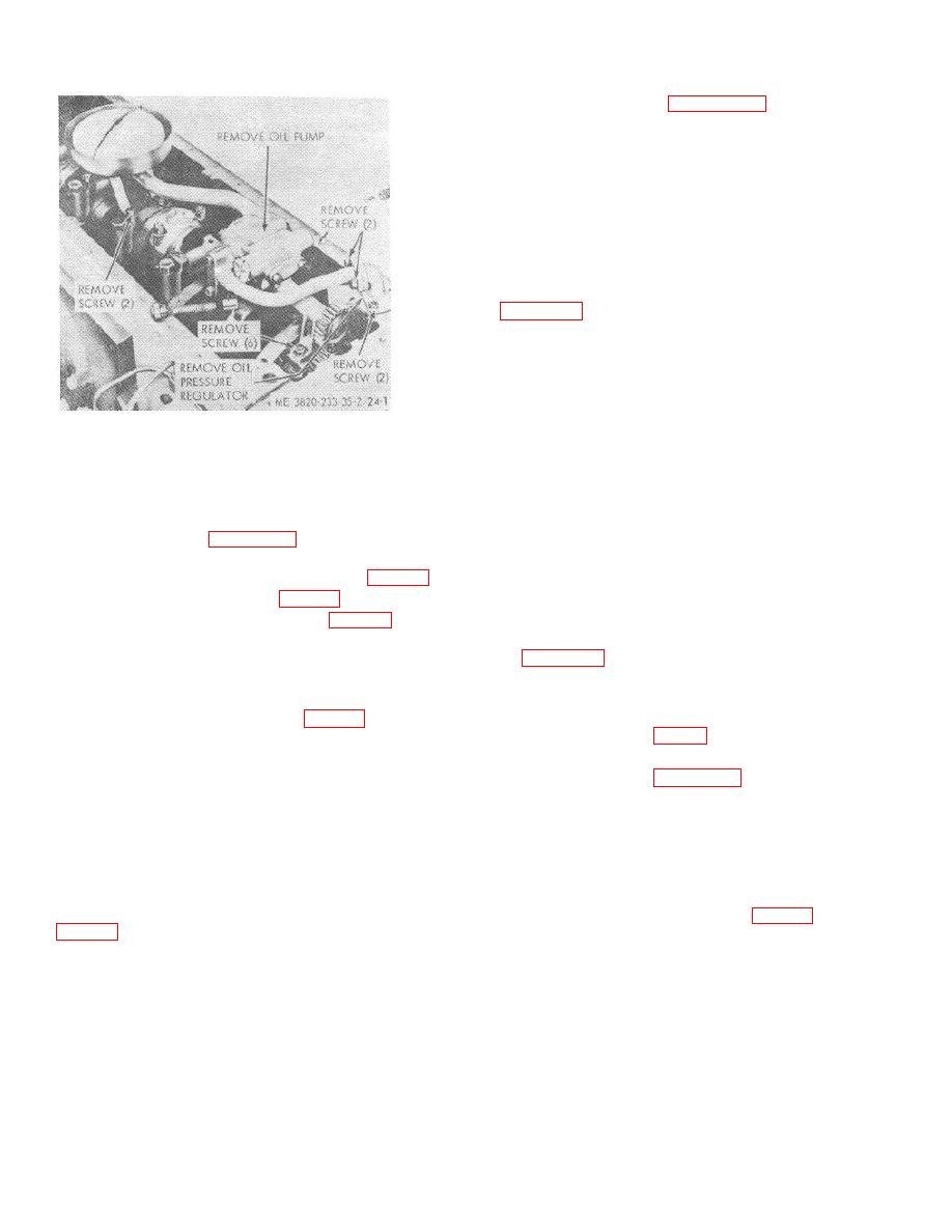
Figure 24-1. Oil pump and pressure regulator
(3) Inspect
clutch
facings
for
wear,
assembly, removal and installation.
overheating, or scoring. Inspect clutch facing teeth for
wear or damage. Replace a defective clutch facing.
f. Installation
(4) Inspect clutch pressure plates for flatness,
cracks, signs of overheating or damage. Replace a
(1) Refer to figure 25-1 and install the piston
defective pressure plate.
and connecting rod assemblies.
(5) Inspect all parts for excessive wear or
(2) Install the lubricating oil pump (para 45).
damage. Replace defective parts as necessary.
(3) Install the oil pan (para 44).
e. Reassembly
(4) In-stall the cylinder head (para 43).
(1) Reassemble the power takeoff assembly
in the reverse of the numerical sequence as illustrated
(5) Ref. to the Operator's Manual and install
on figure 26-2.
the hoods, side panels, and tie rods.
(2) After the clutch has been assembled keep
(6) Refer to the Operator's Manual and install
it engaged until the power takeoff is assembled to the
the muffler and air cleaner.
engine.
(7) Install the power unit (para 23).
(3) Refer to para 4 for torque data.
(8) Refill with engine oil (Operator's Manual).
f. Installation
47. Power Takeoff Assembly
(1) Refer to figure 26-1 and install the power
takeoff assembly.
(2) Install pulley to the drive shaft.
a. General. The power takeoff is used to engage
and disengage the engine power to the plant. The
(3) Refer to the Operator's Manual and install
power takeoff clutch is a 14 inch, three piece single
the hoods, side panels, and tile rods.
plate, dry disc type.
(4) Refer to the Operator's Manual and install
b. Removal
the air cleaner and muffler.
(1) Remove the power unit from the plant
(5) Install the power unit (para 23).
48. Flywheel and Flywheel Housing
(2) Remove the air cleaner and muffler
(Operator's Manual).
(3) Remove the hoods, side panels, and tie
a. General.
The engine flywheel housing is
rods (Operator's Manual).
mounted on the cylinder block rear end plate and serves
as the housing for the flywheel and gear train. The
(4) Remove pulley from the drive shaft.
flywheel is bolted and doweled securely to the end of the
crankshaft. A steel ring gear is shrunk fit onto the rim
3-33


