
TM 5-3820-233-35/2
Figure 22-2-Continued
(2) Remove the power unit (para 23).
(3) Remove the muffler and air cleaner
(Operator's Manual).
(4) Remove the hoods, side panels, and tie
rods (Operator's Manual).
(5) Remove the cylinder head (para 43).
(6) Remove the oil pan (para 44).
(7) Remove the lubricating oil pump (para
(8) Refer to figure 25-1 and remove the
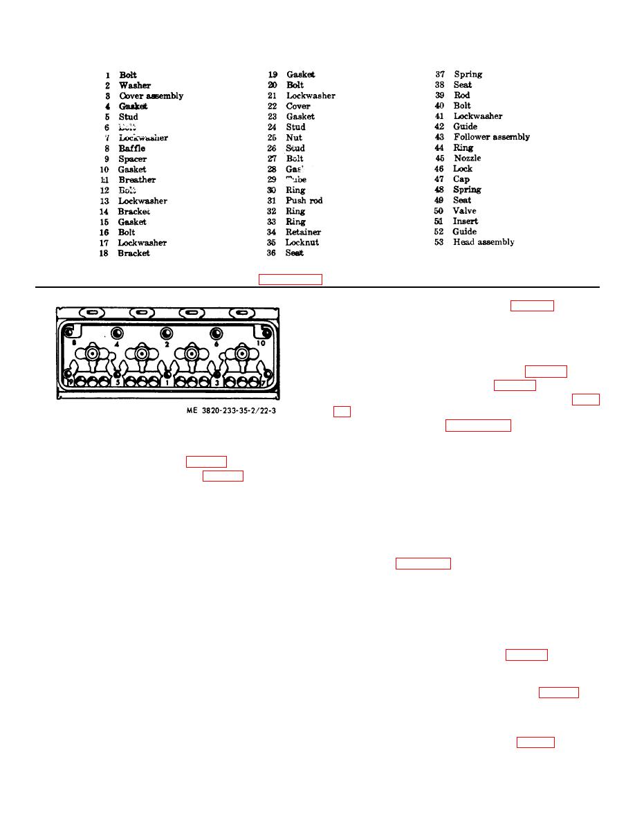
Figure 22-3. Cylinder head tightening sequence.
piston and connecting rod assemblies.
(2) Install the oil pan (para 44).
Note
Ridge ream carbon deposits from the
(3) Install the power unit (para 23).
upper inner surface of the cylinder
(4) Refill with engine (Operator's Manual).
liner before removing the piston and
connecting rod assemblies.
46. Piston and Connecting Rod Assemblies
c. Disassembly.
Disassemble the piston and
a. General.
The piston and connecting rod
connecting rod assemblies in the numerical sequence as
assemblies consist of the pistons, pins, bushings, piston
illustrated on figure 25-2.
d. Cleaning, Inspection, and Repair
six rings each, four above the piston pin and two below.
The rings above the pin are compression rings which
(1) Clean all parts with an approved cleaning
form an airtight seal between the pistons and cylinder
solvent and dry thoroughly.
liners. The rings below the pin are oil control rings
(2) Inspect the pistons for wear, cracks,
which scrape 'the excess oil from the cylinder wall.
scoring and damage. Replace a defective piston.
(3) Measure the pistons and bore in the
b. Removal
cylinder sleeves for clearance (table 1).
Replace
defective parts.
(4) Inspect the piston rings for fit in the
(1) Drain the engine oil (Operator's Manual).
grooves, clearance, and wear. Refer to table 1 for
tolerances.
Replace defective piston rings as
necessary.
(5) Inspect and measure the inside dimension
of the piston pin bushings for wear (table 1). Replace
defective bushings as necessary.
3-31
