
TM 5-3820-233-35/2
Figure 20-Continued
(2) Disassemble the cylinder head in the
numerical sequence as illustrated in fig. 22-2.
d. Cleaning, Inspection, and Repair
(1) Clean all parts with an approved cleaning
solvent and dry thoroughly.
(2) Inspect the cylinder head for cracks or
damage. Replace a cracked or damaged cylinder head.
(3) Check the bottom of the cylinder head for
warpage. The warpage limits are as follows:
Maximum longitudinal Warpage.
0.008 inch
Maximum Transverse Warpage.
0.004 inch
Replace the cylinder head if warpage is beyond the
limits specified.
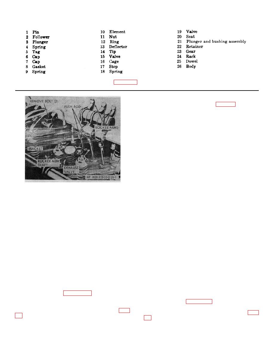
STEP 1. FOLD BACK ROCKER ARMS.
(4) Check the clearance between the valves
STEP 2. REMOVE ROCKER ARM SHAFT AND
and valve guides. Replace the guides if the clearance
BRACKETS.
exceeds 0.006 inch.
STEP 3. DISCONNECT PUSH ROD FROM ROCKER
(5) Inspect valve seats and injector tubes for
ARMS.
signs of over heating, looseness, excessive wear or
STEP 4. REMOVE ROCKER ARMS
other damage. Replace defective parts.
(6) Inspect the valves for cupped, pitted,
Figure 21-1. Rocker arms and shaft, removal and
burned or worn conditions. Grind the valves and reseat
installation.
the inserts to an angle of 30 degrees. Replace parts as
necessary.
(8) Remove the fuel oil filter (Operator's
(7) Inspect the valve springs for excessive
Manual).
wear and replace as necessary.
(9) Disconnect the governor fuel rod from the
(8) Inspect the cylinder head surface for
injector control tube lever. Remove the governor
pitting, scratches, or other damage. Resurface the head
subcap and fuel rod (Operator's Manual).
or replace as necessary.
(10) Remove the fuel injectors and injector
e. Reassembly
control tube (Operator's Manual).
(1) Reassemble the cylinder head in the
(11) Remove the instrument panel and throttle
reverse numerical sequence as illustrated on figure 22-
control rods (Operator's Manual).
2.
(12) Refer to figure 22-1 and remove the
(2) Follow the cylinder head tightening
cylinder head.
sequence shown on figure 22-3. Torque head bolts to
c. Disassembly
175-185-ft. lb.
(1) Remove the rocker arms and shafts (para
(3) Install the rocker arms and shafts (para
3-27
