
TM 5-3820-233-35/2
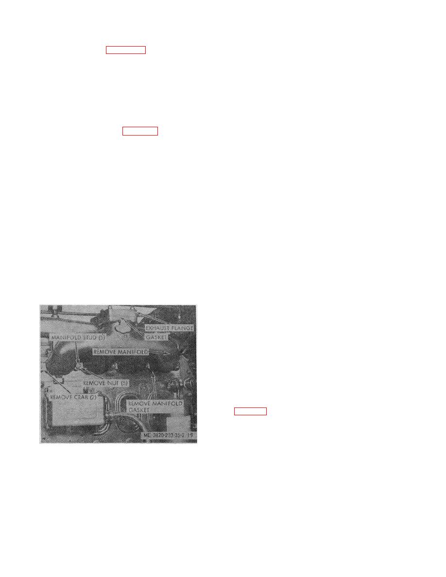
(2) Refer to figure 19 and remove the
c. Bench Testing
exhaust manifold.
(1) Test the spray tip runout with a dial
c. Cleaning and Inspection.
indicator. Total runout must not exceed 0.008 inch. If
the runout exceeds 0.008 inch, loosen retaining nut and
(1) Remove loose carbon deposit and other
recenter nozzle tip in the nut. Tighten nut and recheck
foreign material from the internal walls of the exhaust
runout. Repeat the procedure until correct runout is
manifold.
obtained.
(2) Inspect exhaust manifold studs for
(2) Hold the injector assembly in a horizontal
damage. If stud threads are stripped, replace the studs.
position with the coupling end of the control rack
Torque new studs to 25-40 foot pounds.
pointing upward. Quickly invert the injector assembly so
the coupling end points downward. The rack should
exhaust manifold.
move freely through its full travel by its own weight. To
(1) Install new exhaust flange and exhaust
correct improper rack travel, loosen the retaining nut,
manifold gaskets.
rotate the tip assembly, tighten nut, and recheck rack
(2) Torque manifold attaching nuts to 30-35
travel. Repeat procedure until proper freedom of travel
foot pounds.
is attained.
(3) Refer to the Operator' Manual and install
s
(3) Install the injector assembly in a holding
device with the top side up. Position the control rack in
to 20-25 foot pounds.
the full fuel position, no fuel position, and midway
between. Depress the follower with the rack in each
41.
Fuel Injector
position. To correct the lack of free return, disassemble
and reassemble the injector assembly and recheck the
a. General. A fuel injector assembly is located in
follower return. Replace if necessary.
each of the four cylinders. The fuel injector creates the
high fuel pressure required from efficient injection,
(4) Install the injector assembly in the injector
meters and injects the exact amount of fuel required to
text fixture. Position the control rack in the full fuel
handle the load on the engine, atomizes the fuel for
position and check each nozzle tip orifice for equal fuel
mixing with the air in the combustion chamber, and
discharge pressure. The pressure should be from 450 to
permits continuous fuel flow.
850 psi.
Valve opening pressure below 450 psi
indicates a defective spring. Replace a defective spring
b. Removal. Refer to the Operator' Manual.
s
or the injector assembly.
(5) Dry the injector assembly with a clean lint-
free cloth. Establish pressure on the injector just below
the injector opening pressure and close the pump valve.
Check the time required for the pressure to drop from
450 to 250 psi. This time should not be less than 40
seconds. If time is less than minimum sited above,
inspect the injector assembly for moist areas and
determine source of leaks. Leakage around the seal
indicates a loose retaining nut. Leakage at the rack
opening in the injector.
d. Disassembly.
Disassemble fuel injector
assembly in the numerical sequence as illustrated in
e. Cleaning, Inspection, and Repair
(1) Clean the fuel injector parts with an
approved cleaning solvent and dry thoroughly.
Figure 19. Exhaust manifold, removal and
installation.
3-24
