TM 5-3820-233-35/2
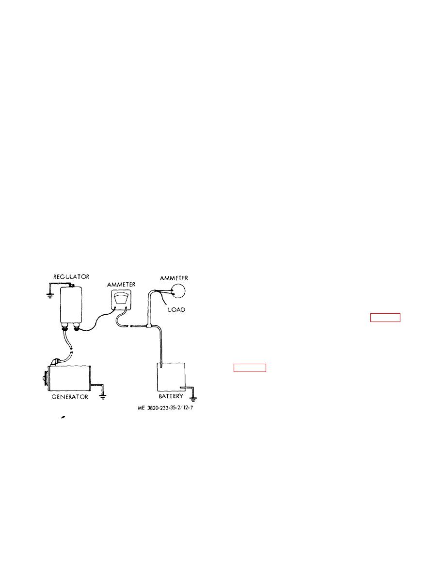
available. Regardless of the method used, disconnect
(c)
Jumper Lead Method. If the
battery cable from the regulator and connect an
regulator cover is removed and a jumper lead placed
accurate ammeter in series between these junctions.
across the voltage regulator contact points, the voltage
This meter will measure the current regulator setting.
regulator cannot operate. Consequently, the generator
The three methods of preventing voltage regulator
output will increase to its maximum as determined by
operation are:
the current regulator setting. Lights and accessories
(a) Battery Discharge Method. By
should be turned on during the test to prevent excessive
this method, the battery is partly discharged by cranking
voltage. To adjust the current regulator setting, turn the
the engine for 30 second with lights, and other
adjusting screw at the base of the tension. Increasing
accessories turned on. NEVER USE THE CRANKING
the tension will increase 'the current setting. After each
MOTOR FOR MORE THAN 30 SECONDS AT A TIME
change of adjustment, reduce generator speed until
WITHOUT PAUSING TO ALLOW THE CRANKING
cutout relay opens, then return to speed and read
MOTOR TO COOL OFF. Excessive cranking will
current. (Higher residual magnetism reseeding from
damage the cranking motor. Immediately after the
uncontrolled voltage during this test will cause the
cranking cycle, start the engine and allow the generator
voltage to regulate at an abnormally low voltage after
output to increase to its maximum as determined by the
the jumper is removed. To restore proper operation, the
current regulator to operate. Since battery voltage
generator must be "cycled", that is, stopped and
recovers very quickly, this method requires prompt
restarted. Do not attempt to check voltage regulator
action.
after using JUMPER LEAD METHOD until this condition
(b) Load Method.
If a load
has been corrected.)
f.
Installation. Refer to Operator's Manual.
approximating the carrier regulator setting is placed
across the battery during the time that the current
regulator setting test is made, the voltage will not
33. Radiator Assembly
increase sufficiently to cause the voltage regulator to
operate. This load may be provided by a carbon pile or
a.
General. The radiator assembly is mounted
other suitable resistance.
on the front of the engine. As the water flows through
the radiator core, it is cooled by air forced through the
core by a belt driven fan. A guard is attached to the fan
shroud to prevent loose clothing, hands, and other ob-
jects from becoming entangled in the fan blades.
b.
Removal and Disassembly
(1) Remove the power unit (para 23).
(2) Drain the radiator.
(3) Remove the hoods, side panels, and
tie rods (Operator's Manual).
(4) Remove and disassemble the radiator
assembly in the numerical sequence as illustrated on
c.
Cleaning, Inspection, and Repair
(1) Flush the inside of the radiator with an
approved cleaning solvent.
(2) Plug the radiator openings. In an air
hose in radiator outlet pipe. Immerse the radiator in
water and apply 85 psi. air. Air
Figure 12-7. Meter connections for current regulator
checks.
3-10


