TM 5-3820-233-35/2
air gap, point opening and closing voltage. Air gap and
point opening are checked with the battery
disconnected.
(a) Air Gap. Measure the air gap
between the armature and the core not between the
brass pin in the armature and the core with the contact
points barely touching. If both sets of points do not
close together, it will be necessary to realign the lower
contact bracket slightly or to bend the spring fingers on
the armature until points do meet simultaneously Adjust
air gap by loosening the two screws attaching the lower
contact bracket, and raise or lower the contact bracket
as required. Be -ire the points are properly lined up and
tighten the screws well after adjustment.
(b) Point Opening. Measure the
point opening and adjust by bending the upper armature
stop.
(c)
Closing Voltage. To check the
closing voltage on the cutout relay, insert Special
Testing Harness No. 1 (fig. 12-5) in the generator
circuit, and connect a voltmeter between T-1 (armature)
and the ground screw (at the end of the regulator (fig.
voltage at which the relay contact points, it is the closing
voltage, if necessary, ring the adjust screen at the cutout
relay frame.
Increasing the spiral spring tension
increases the relay closing voltage decreasing the spiral
spring tension lowers the closing voltage.
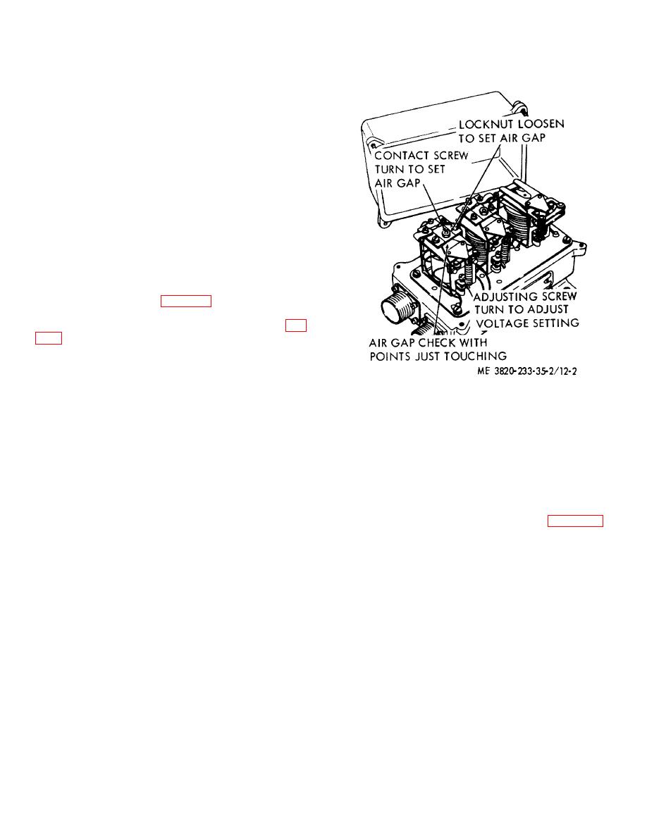
Figure 12-2. Voltage and current regulator ad-
(2) Voltage Regulator. Two checks and
justments.
adjustments are required on the voltage regulator: air
gap and voltage setting. Attention is called to fact that
ing plate. To adjust, loosen the locknut and turn the
the AIR GAP and not the POINT OPENING is checked
contact screw.
The most convenient method of
and adjusted.
performing this operation is to insert the gage, press the
(a) Air Gap. The air gap should be
armature down against it to hold it in pace, and then turn
measured between the armature and the part of the core
the contact screw until the contacts barely touch.
(not the residual pin in the core) next to the residual pin,
with the points just touching. The proper way to
measure this air gap is to push the armature down until
Disconnect battery cable from regulator, and connect
the points open, release until the points barely close,
voltmeter between regulator battery terminal, and
then measure the air gap. Do not measure the gap with
ground screws in the end of the regulator. With the
the flat spring that supports the contact s raised up off
generator operating at approximately 3000 RPM and the
the fiber mount-
regulator at operating temperature, note the voltage
setting. Adjust by turning the adjusting screw at the
base of the unit, thereby changing the spiral spring
,tension. Increasing the spring tension increases the
voltage setting. After each change of adjustment,
reduce generator speed until cutout relay opens; then
return to speed and read voltage.
3-8


