
TM 5-3820-233-35/2
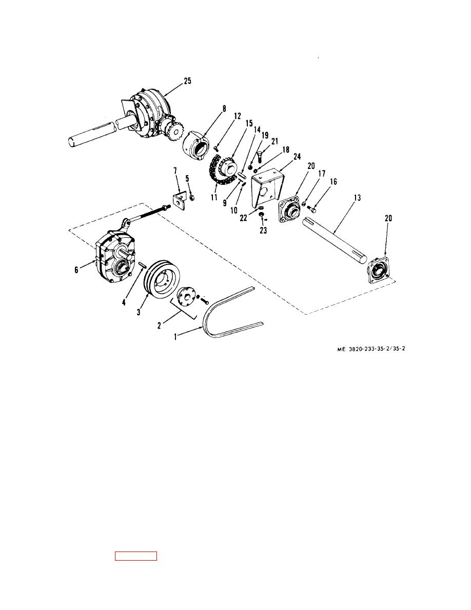
1
V-Belt
10
Clip
19
Nut
2
Bushing
11
Chain
20
Bearing assembly
3
Pulley
12
Setscrew
21
Capscrew
4
Key
13
Shaft
22
Lockwasher
5
Nut
14
Key
23
Nut
6
Speed reducer
15
Coupling
24
Support
7
Support
16
Capscrew
25
Gear box
8
Coupling
17
Washer
9
Pin
18
Lockwasher
Figure 35-2. Sand conveyor drive, exploded view.
Note
h. Speed Reducer Reassembly.
Install grease seals so knife edge of
(1) Reassemble speed reducer in the reverse
the seals contacting revolving shaft
of the numerical sequence as illustrated on figure 35-3.
and coupling is turned in toward
Follow the instructions below when installing gears and
center of gear box.
(a) Heat gear (31) in oil (325oF-50oF) to
(2) Fill gear box with lubricant (Operator's
shrink onto hub (34).
Manual).
g. Bearing Reassembly.
Reassemble
the
assembly as illustrated on figure 35-4.
4-9
