TM 5-3820-233-35/2
(2) Refer to the Operator's Manual and make
the necessary belt tension adjustments.
(3) Install the main countershaft-to-lower
countershaft guard, and the lower countershaft-to-sand
conveyor drive guard.
60. Rock Conveyor Drive
The rock conveyor drive is shown installed on figure 36-
1. Remove, disassemble, repair, reassemble, and
install the rock conveyor drive (fig. 36-2) in the same
manner as discussed under 'Sand Conveyor Drive".
Refer to the Operator's Manual and remove the screen
and screen countershaft guard, and the idler-to-rock
conveyor drive guard. Be sure to install guards after
installation and reassembly.
61. Screen rind Side Conveyor Countershaft Drive
a. Removal and Disassembly.
(1) Remove the main countershaft-to-lower
countershaft guard, and the screen and screen
countershaft guard (Operator's Manual).
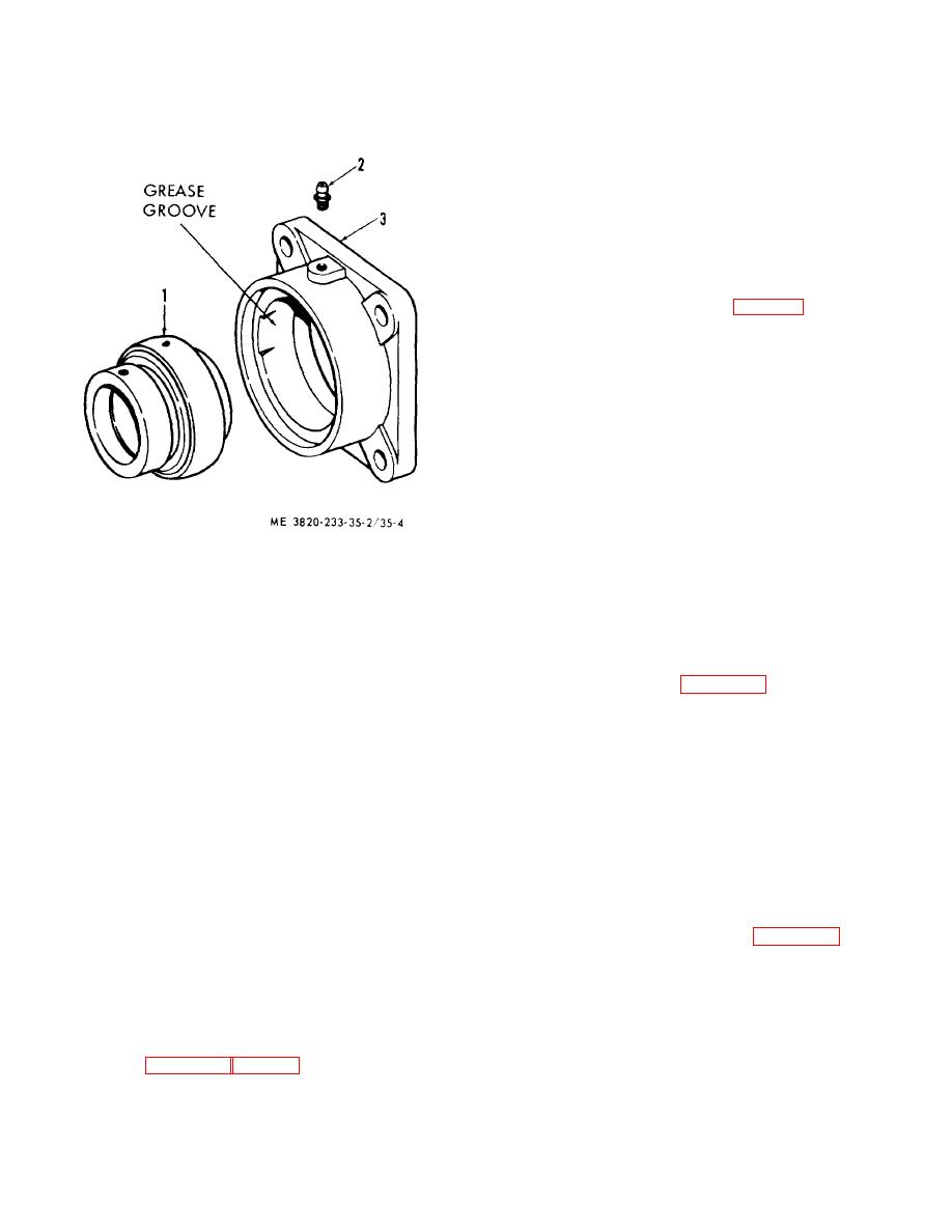
1 Bearing
2 Fitting
3 Housing
(2) Remove the clutch controls and twin-disc
clutch assembly (Operator's Manual).
Figure 35-4. Bearing assembly, exploded view.
(3) Remove and disassemble the screen and
side conveyor countershaft drive assembly as illustrated
o
on figure 37-1.
(b) Heat bearings (30) in oil (270 F-
o
290 F) to shrink onto hub (34).
b. Twin-Disc Clutch Disassembly. Disassemble
the twin-disc clutch assemblies in the numerical
sequence as illustrated on figure 37-2.
Caution
Any injury to the hub surfaces where
c. Bearing Disassembly. Bearing assemblies (82
the oil seals (28 and 40) rub will
and 104, fig. 37-1) are identical to those illustrated on
figure 34-3.
cause leakage, and a new hub will
have to be installed.
d. Cleaning, Inspection, and Repair.
(1) Clean all parts in an approved cleaning
Note
solvent and dry thoroughly.
Wheel pressing bearings (36 and 36)
(2) Inspect all parts for wear and damage.
on shaft (39), press against the inner
Replace or repair all defective parts.
race, not the outer race, of the
e. Bearing Reassembly.
Reassemble bearing
hearings.
assemblies as illustrated on figure 34-3.
f. Twin-Disc Clutch Reassembly. Reassemble the
(2) Fill cavity between the oil seals and
twin-disc clutch assembly in the reverse of the
housing bores with chassis grease to prevent oil
numerical sequence as illustrated on figure 37-2.
leakage.
g. Reassembly and Installation.
(3) Fill speed reducer with lubricant
(1) Reassemble and install the screen and
(Operator's Manual).
side conveyor countershaft drive assembly as illustrated
i. Installation and Reassembly
on figure 37-1.
(1) Reassemble and install sand conveyor
(2) Install the twin-disc clutch assembly and
drive in the reverse of the numerical sequence as
clutch controls (Operator's Manual).
illustrated on figures 35-1 and 35-2.
4-11


