
MAINTENANCE AND SERVICE
The instructions contained herein cover the disassembly
and reassembly of the transmission mounted hydraulic
brake. The unit shown has been removed from the
machine and the brake is to be completely overhauled. If
clearance will allow the brake can be repaired in the
machine.
The brake assembly shown is a unit without unidirectional
power take off. If a P.T.O. was used it is not necessary to
remove the companion flange unless the hydraulic brake
cover and valve assembly is to be replaced.
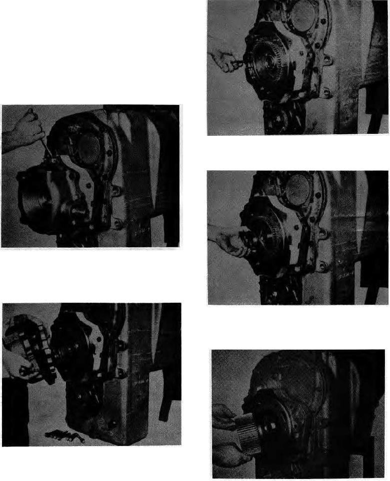
Figure 3
Remove return springs and pins from disc housing.
Figure 1
Remove the brake cover bolts evenly around the brake
cover as the return springs will push the cover away from
the disc housing.
Figure 4
Secure output shaft to prevent turning and remove disc hub
nut.
Figure 2
Remove brake cover assembly and end plate from disc
housing.
Figure 5
NOTE: If P.T.O. is used pull cover straight out to remove
Remove disc hub.
P.T.O. shaft from idler shaft.
1