showing indication of wear or stress will eliminate costly
and avoidable failures at a later date.
Housing, Covers, etc.
Inspect housings, covers and bearing caps to be certain
they are thoroughly cleaned and that mating surfaces,
bearing bores, etc., are free from nicks or burrs. Check all
parts carefully for evidence of cracks or condition which
would cause subsequent oil leaks or failures.
O-Rings
Replacement of O-Rings is more economical when unit is
disassembled than premature overhaul to replace these
parts at a future time. Further loss of lubricant through a
worn seal may result in failure of other more expensive
parts of the assembly. Sealing members should be
Figure 13
handled carefully, particularly when being installed.
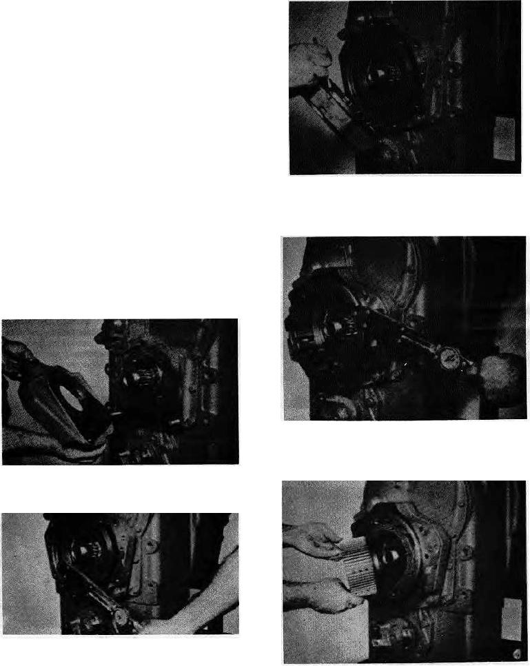
Install a new brake disc housing O-Ring and position disc
Cutting or scratching, seriously impairs its efficiency.
housing on adaptor.
Lubricate all O-Rings and seals with recommended type
Automatic Transmission Fluid before assembly.
When cleaning and replacing parts in the hydraulic brake
cover and valve assembly refer to Figure A for Location
and sequence of parts.
REASSEMBLY
Figure 14
Install disc housing to adaptor bolts and tighten 37 to 41
ft.lbs. torque [5,1-5,6 mm].
Figure 11
Using new O-Rings, position brake housing adaptor on
transmission.
Figure 12
Install adaptor to transmission place bolts and washers
(Qty. 4 each). Install stud nuts and washers (Qty. 2 each).
Tighten place bolts 115 to 127 ft.-lbs. Torque [15,9-17,5
Figure 15
mm] tighten stud nuts 180 to 198 ft.-lbs. torque
Align brake disc hub splines with idler shaft splines and
[24,9-27,3 mm].
install disc hub and disc hub nut.
3

