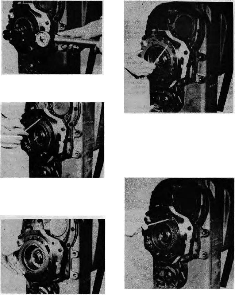
Figure 16
Block, output shaft and tighten disc hub nut 250 to 30C ft.-
lbs. torque 134,6-41,4 mm].
Figure 19
Move the second steel disc one spline to the right. This
misaligns the first steel disc and the second steel disc by
one spline. Another mark (x) was made and this mark
must be used during the remainder of the assembly. This
marked area and five other places will allow passage for
the six return springs with the springs bottoming on the
teeth of the first steel disc. Alternate friction and steel
discs being certain the splines on each steel disc are
aligned with the splines on the previous steel disc.
Figure 17
Install one steel disc (splined on the outer diameter) into
disc housing. A mark (x) was made on the disc housing in
a space between a two spline section and a three spline
section.
Figure 20
Figure 20 shows the return springs and pins to the spring
Figure 18
passages.
Install one frictional disc (splines on the inner diameter)
against first steel disc.
4

