
Section III. ENGINE LUBRICATION SYSTEM
66. General
68. Oil Cooler Bypass Valve
The engine lubrication system is a pressurized-type. A
a. Removal and Disassembly.
Remove and
gear-type oil pump attached to the bottom of the engine
disassemble the oil cooler bypass valve as illustrated on
crankcase provides oil under pressure from the engine
oil pan to the moving parts of the engine. The oil cooler
b. Cleaning and Inspection. Clean and inspect all
bypass valve allows the engine oil to continue to flow
parts. Replace all damaged parts as necessary.
through the lubrication system should the oil cooler
c. Reassembly and Installation. Reassemble and
become clogged. The engine oil is filtered by three oil
install the oil cooler bypass valve illustrated on figure
filters.
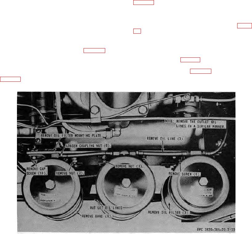
67. Oil Filters and Mounting Bracket
69. Oil Cooler
a. Removal. Remove the oil filter and mounting
a. Removal.
bracket from the engine as instructed on figure 23.
(1) Remove the oil filters and mounting
b. Cleaning and Inspection. Clean and inspect the
bracket (para. 67).
oil filters and bracket. Replace all damaged parts.
(2) Remove the oil cooler from the engine as
c. Installation. Install the oil filters and mounting
instructed on figure 25.
bracket on the engine in reverse of the instructions on
b. Cleaning and Inspection. Clean and inspect the
oil cooler. Replace if necessary.
Figure 23. Oil filters
mounting bracket, removal and installation.
AGO 8157A
42