
(2) Install the engine housing door supports
c. Installations.
(3) Install the muffler assembly (para. 73).
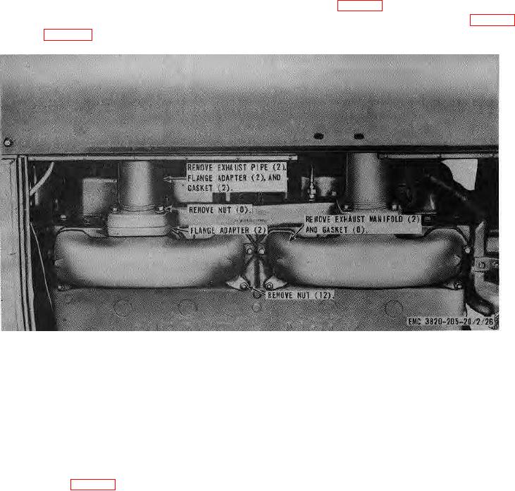
the engine in reverse of the instructions
on figure 26.
Section V. ENGINE ELECTRICAL SYSTEM
75. General
(2) Use a voltmeter to test each cell for
The electrical system of the roll crusher is a 24-volt
voltage. Each full charged cell must
system which consists of four batteries, generator,
deliver two volts. A low voltage indicates
generator regulator, starter, oil pressure gage and
a low charge or a defective cell.
sending unit, water temperature gage and sending unit,
Recharge the batter, if the output voltage
battery indicator gage, safety governor, safety ignition
varies more than 30 percent between
switch, and the necessary wiring and connectors to
cells, replace the battery.
complete the system. Figure 1 is the wiring diagram for
Warning
the roll crusher electrical system.
Do not smoke or allow an open flame
near charging batteries.
Serious
76. Batteries and Cables
injury from explosion and acid could
a. Testing.
result. Avoid spilling electrolyte on
(1) Use a hydrometer to test each battery
clothing or flesh.
Acid causes
cell; each cell should read 1.280 specific
severe burns.
gravity at 80 F. Recharge if the reading is
b. Removal.
1.250 or less.
(1) Loosen locknut (fig, 27) and place clamp
handle up or at right angle to battery
terminal.
AGO 8157A
45