
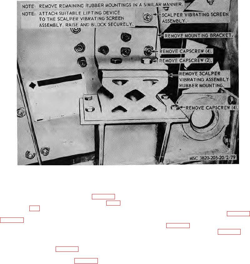
Figure 106. Rubber mountings, removal and installation.
b. Cleaning, Inspection, and Repair. Clean and
c. Installation..
inspect all parts. Replace all damaged or defective
(1) Install the slack adjuster on the unit ill
parts as necessary.
reverse of the instructions on figure 113.
c. Installation.
(2) Connect linkage to air chamber (para.
(1) Install the brake assembly on the axle in
reverse of the instructions on figure 112.
d. Adjustment. Adjust the brakes as instructed on
(2) Install the hub assembly and brakedrum
179. Brake Assembly
d. Adjustment. Adjust the brakes (para. 175).
a. Removal.
(1) Remove the wheel hub assembly and
brakedrum (para. 177).
(2) Remove the brake assembly from the
axle as illustrated on figure 112.
139