
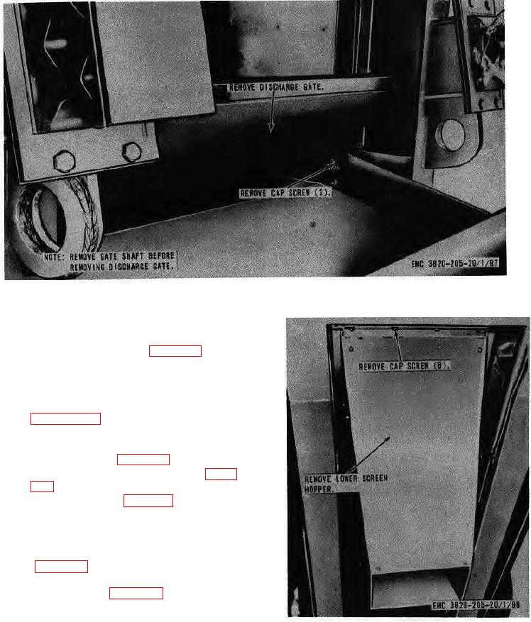
Figure 103. Discharge gate, removal and installation.
(2) Remove the wheel hub assembly.
(3) Remove the brakedrum and slinger from
the hub as illustrated on figure 112.
b. Cleaning and Inspection.
(1) Clean and inspect all parts. Replace
defective parts.
(2) For lubrication of wheel bearing refer to
c. Installation.
(1) Install the brakedrum and slinger on the
hub illustrated on figure 112.
(2) Install the wheel hub assembly (para.
(3) Install the wheels (para. 111).
178. Slack Adjuster
a. Removal.
(1) Disconnect the linkage from air chamber
(2) Remove the slack adjuster from the unit
as instructed on figure 113.
b. Cleansing and Inspection. Clean and inspect all
parts. Replace defective or damaged parts.
Figure 104. Lower screen hopper-, removal and
installation.
AGO8157A
137