
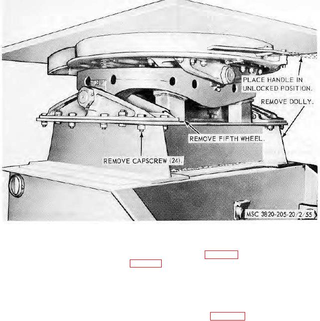
Figure 55. Fifth wheel and dolly assembly, removal and installation.
e. Installation.
(1) Install the fifth wheel in reverse of instructions on figure 55.
(2) Install the dolly assembly (par. 113).
115. Dolly Wheels and Tires
a. Removal.
(1) Use a suitable lifting device and place dolly axle on blocks.
(2) Remove the dolly wheels and tires as instructed on figure 57.
b. Cleaning, Inspection, and Repair.
(1) Clean studs and nuts with an approved cleaning solvent and dry thoroughly.
(2) Clean hub, wheel faces, and nut cavities of all paint and preservation before installation.
(3) Clean and inspect wheels and tires. Replace defective wheels and tires. Repair tires and
tubes as instructed in TM 9-1870-1.
c. Installation.
(1) Install inner wheel on hub.
Note. Number the studs 1 to 6.
(2) Install inner capnuts on studs 1 and 4 and torque to 150 to 200 foot-pounds.
(3) Install the remaining capnuts and torque Nos. 2, 5, 3, and 6 to 500 to 600 foot-pounds in
that order. Retorque Nos. 1 and 4 to 500 to 600 foot-pounds.
(4) Install the outer wheel assembly making sure that the outer wheel valve stem is opposite
the inner valve stem.
(5) Install two outer nuts on opposite studs (WITHOUT THE WASHERS INSTALLED) and
torque to 150 to 200 foot-pounds.
(6) Install the four remaining outer nuts (WITH WASHERS INSTALLED)
AGO 8156A
76