
Figure 57. Dolly wheel, removal and installation
and torque to 500 to 600 foot-pounds in the sequence outlined above.
(7) Remove the two outer nuts (5) above and reinstall with washers and torque to 500 to 600 foot-
pounds.
(8) Remove the dolly from the blocks using a suitable lifting device and road test approximately 10
miles. After first mile, fifth mile, and tenth mile retorque inner and then outer nuts to 500 to 600 foot-pounds.
If at the tenth mile torque value has dropped below 400 foot-pounds, remove wheels, investigate, and repeat
entire procedure.
Caution: A trestle (Motor Vehicle Maintenance, 5-ton) will be used in final torquing
operations, taking care that drive extensions are parallel to the ground at all times.
116. Wheel Bearing and Hub Assemblies
a. Removal and Disassembly.
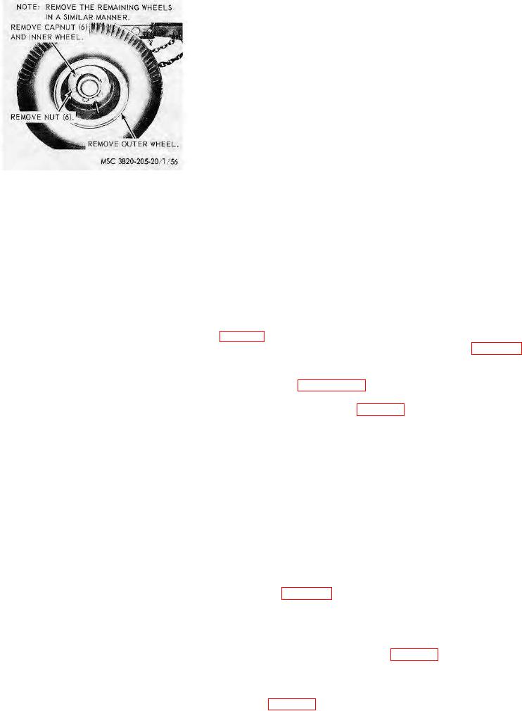
(1) Remove the dolly wheels (par. 115).
(2) Remove and disassemble the wheel bearings and hub assembly as illustrated on figure 58.
b. Cleaning, Inspection, and Repair.
(1) Clean and inspect all parts. Replace defective parts as necessary.
(2) Service the wheel bearings as instructed in paragraph 17.
c. Reassembly and Installation.
(1) Install the bearings and hub on the axle as illustrated on figure 58.
Note. Install hubs with right-hand stubs on right side of the vehicle and hubs with left-
hand studs on left side of the vehicle.
(2) Install the wheel bearing adjusting nut. Screw the nut against the bearing as the wheel is
resolved. Be sure there is sufficient clearance between the brakeshoe and drum so brakeshoe drag will
not interfere with the bearing adjustment.
(3) Tighten the adjusting nut to 50-foot-pounds torque while the wheel is being rotated. Rotate
the wheel in both directions to correctly position the bearings.
(4) Back off adjusting nut /6 to % turn, and install the adjusting nut lockwasher. If the holes in
lockwasher do not fit dowel protruding from adjusting nut, the washer may be removed and turned
over, which changes hole locations.
(5) Install the outer locknut and torque to 250 to 400 foot-pounds.
Note. The use of an impact wrench is discouraged; however, if used, the final
torquing will be accomplished by hand using a smooth downward effort.
117. Air Hoses and Fittings
a. Removal. Remove the air hoses as illustrated on figure 59.
Note. On units of equipment within serial No. range 2090 through 2129 the hoses and
cable are suspended by the Flexo-Stick assembly.
b. Cleaning and Inspection. Clean and inspect all air hoses and fittings for damage or deterioration.
Replace as required.
c. Installation. Install the air hoses and fittings in reverse of instructions on figure 59.
118. Drawbar
a. Removal.
(1) Remove Flexo-Stick assembly from drawbar (TM 5-3820-205-10/2).
(2) Remove the drawbar as instructed on figure 59.
AGO 8156A
78