
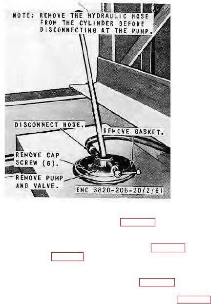
Figure 66. Hydraulic hose, pump, and valve, installed view
(2) Remove the hydraulic tank and bracket as instructed on figure 68.
b.
Cleaning and Inspection. Clean and inspect all parts. Replace all damaged parts.
c.
Installation.
(1) Install the hydraulic tank and bracket in reverse of instructions on figure 68.
(2) Install the hose, pump, and valve (par. 135).
137.
Hydraulic Cylinder and Hose
a.
Removal. Remove the hydraulic cylinder and hose as instructed on figure 69.
b.
Cleaning and Inspection. Clean and inspect all parts. Replace all damaged parts.
c.
Installation. Install the hydraulic cylinder and hose in reverse of instructions on figure 69.
AGO 8165A
90