
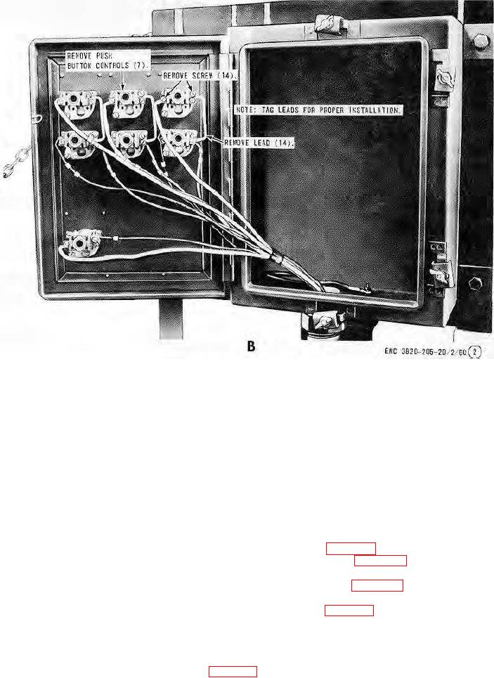
B-Operator's control box rear view
Figure 65-Continued.
Section II. HYDRAULIC SYSTEM
134.
General
The crusher hydraulic system includes a tank with an internally mounted, hand operated pump. A hose with a
manually operated valve connects the pump to the five stage hydraulic cylinder used to raise or lower the pan feeder
assembly.
135.
Hydraulic Hose, Pump, and Valve
a.
Removal.
(1) Drain the hydraulic system (TM 5-3820-205-10/2).
(2) Remove the hydraulic hose, pump, and valve as illustrated on figure 66.
b.
Disassembly. Disassemble the hydraulic pump and valve as illustrated on figure 67.
c.
Cleaning, Inspection, and Repair. Clean and inspect all parts. Replace or repair all damaged parts.
d.
Reassembly. Reassemble the hydraulic pump and valve as illustrated on figure 67.
e.
Installation.
(1) Install the hose, pump, and valve in reverse of instructions on figure 66.
(2) Fill the hydraulic system (TM 5-3820-205-10/2).
136.
Hydraulic Tank
a.
Removal.
(1) Remove the hose, pump, and valve (par. 135).
AGO 8165A
89