
Section III. AIR SYSTEM
138.
General
The air system consists of the hose, lines, valves, filters, chambers, and air tank. The air system is used to actuate
the brakes when the jaw crusher is being towed from one location to another.
139.
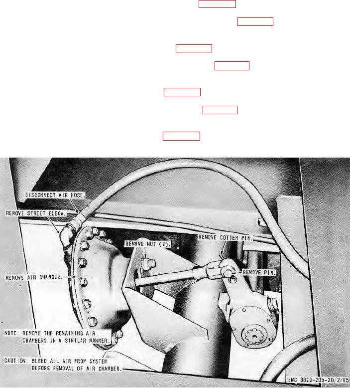
Air Brake Chamber
a.
Removal. Remove the air brake chamber as instructed on figure 70.
b.
Cleaning and Inspection. Clean and inspect all parts. Replace a defective air brake chamber.
c.
Installation. Install the air brake chamber in reverse of instructions on figure 70.
140.
Relay Valve
a.
Removal. Remove the relay valve as instructed on figure 71.
b.
Cleaning and Inspection. Clean and inspect the relay valve. Replace a defective relay valve.
c.
Installation. Install the relay valve in reverse of instructions on figure 71.
141.
Air Filter
a.
Removal. Remove the air filter as instructed on figure 72.
b.
Cleaning and Inspection. Clean and inspect the air filters. Replace a defective filter.
c.
Installation. Install the air filter in reverse of instructions on figure 72.
142.
Air Tank
a.
Removal. Remove the air tank as instructed on figure 73.
b.
Cleaning and Inspection. Clean and inspect the air tank. Replace a defective air tank.
1 Serial No. Range 2050 through 2087
Figure 70. Air brake chamber, installed view.
AGO 8165A
93