Home
Download PDF
Order CD-ROM
Order in Print
Figure 67. Hydraulic pump and valve, exploded view.
Figure 70. Air brake chamber, installed view.
Maintenance Manual For Crusher, Roll: Diesel And Electric Driven, Pneumatic Tires, 75 Ton Per Hour - Vol2
Page Navigation
85
86
87
88
89
90
91
92
93
94
95
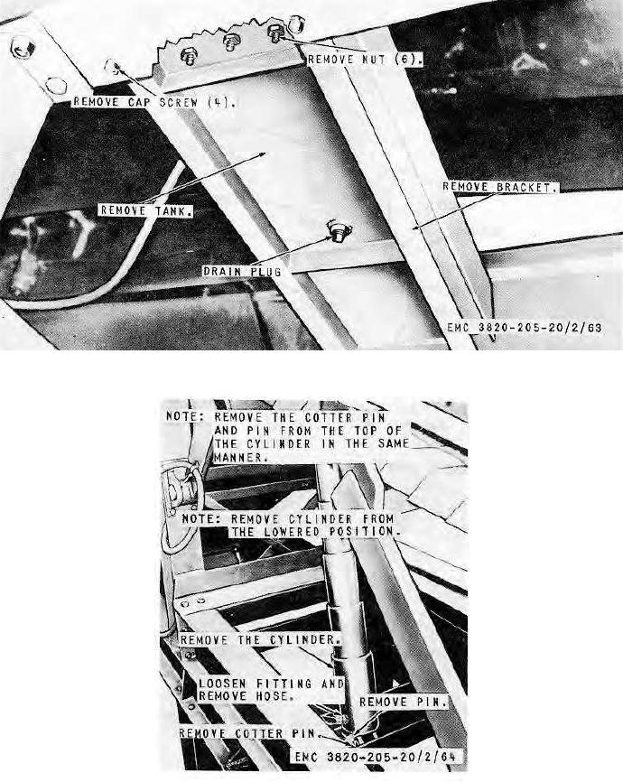
Figure
68.
Hydraulic
tank
and
bracket,
installed
view.
Figure
69.
Hydraulic cylinder
and
hose,
installed
view.
AGO
8165A
92