
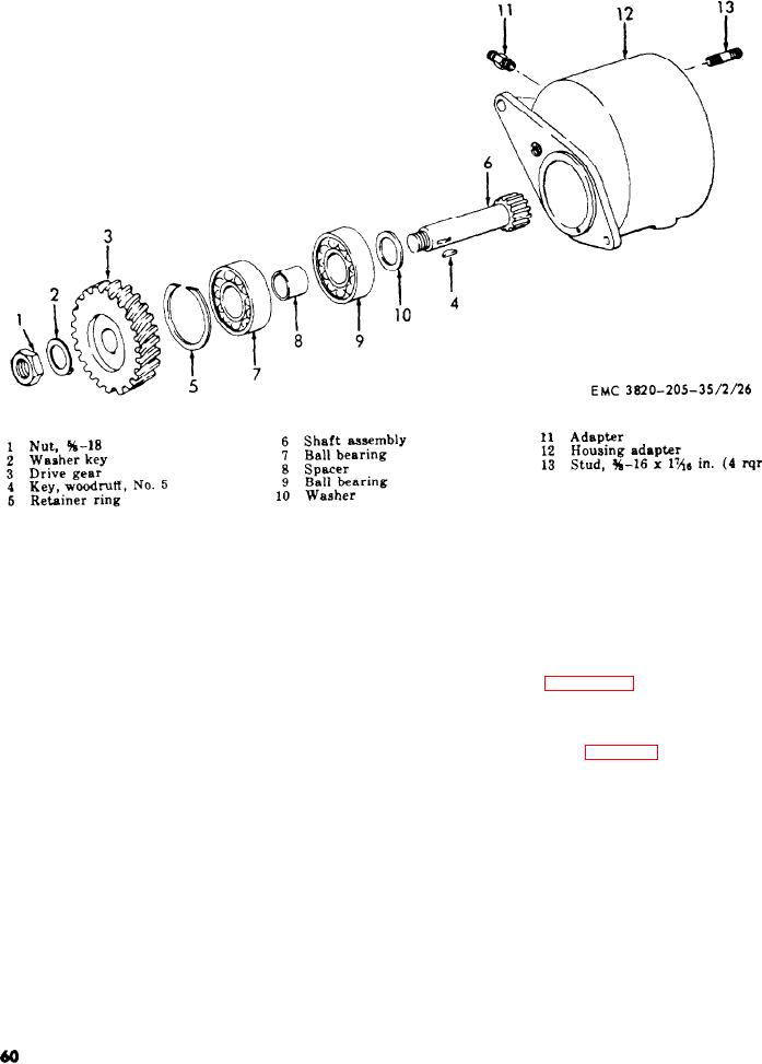
Figure 22. Injection pump drive gear assembly, exploded view.
Se c t ion
X.
ROCK ER
ARM
ASSEM BLY
( 2 ) Remove the cylinder head covers (TM
73. General
5-3820-205-20/l).
The rocker arm assembly is comprised of two
(3) R e f e r t o f i g u r e 2 3 , a n d r e m o v e t h e
s h a f t s on which are mounted 12 rocker arms
r o c k e r arm assembly and push rode
a n d 8 shaft springs. The shafts are mounted
from the engine.
o n six brackets and the brackets are mounted
b. Disassembly. Refer to figure 24, and dis-
on the cylinder heads. Six studs inserted
assemble the rocker arm assembly.
through the brackets and shafts prevent the
s h a f t from turning and also mount the rocker
75. Rocker Arm Assembly Cleaning,
arm shaft assembly securely on the cylinder
Inspection, and Repair
head. The rocker arm shaft assembly is lubri-
cated by means of oil galleries located on the
a. Cleaning. Clean all parts with an ap-
cylinder heads.
proved cleaning solvent and dry thoroughly.
b. Inspection and Repair.
74. Rocker Arm Assembly Removal
and Disassembly
(1) Inspect the rocker arm shaft for wear
or distortion.
a.
Removal.
( 2 ) Inspect the rocker arms for wear on
(1) Remove the engine housing (TM 5-
the contact surface.
3820-205-20/1).
AGO 8498A
60