
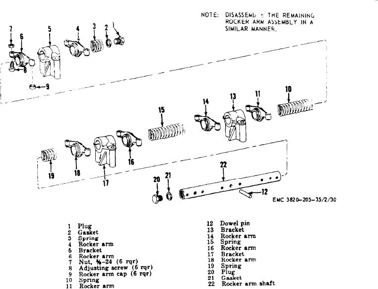
Figure 24. Rocker arm assembly, exploded view.
Se c t ion
I.
CY LI N DER
H EAD
ASSEM BLY
fuel in the energy cell likewise ignites, but due
7 7 . General
to the design of the cell, the pressure is trapped
The engine has two cylinder head assemblies.
a n d is permitted to expand only through the
Each cylinder head assembly covers three cyl-
metered opening, back to the combustion cham-
i n d e r s . The cylinder head assembly contains
ber where its modified force against the head
the intake and exhaust valves, the rocker arm
of the piston continues well through the power
a s s e m b l y , and the energy cells. The cylinder
stroke.
heads are water-cooled and also have oil gal-
l e r i e s which lubricate the rocker arm mecha-
7 8 . C y l i n d e r Head Assembly Removal
nisms. The energy cells are located in the cyl-
a n d Disassembly
i n d e r head directly opposite the fuel injector
nozzle. The fuel is injected by the fuel injector
a. Removal.
into the combustion chamber and energy cells.
(1) Remove the engine housing (TM 5-
The fuel which is in the combustion chamber is
3820-205-20/1).
ignited and starts the combustion. The air and
AGO 8498A