
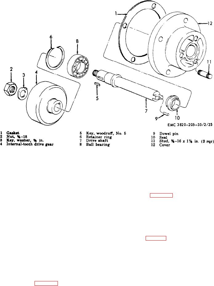
Figure 21. Injection pump drivc shaft assembly, exploded view.
71. Injection Pump Drive Shaft and Drive
i n j e c t i o n pump drive gear in the re-
v e r s e order.
Gear Assemblies, Cleaning, Inspection,
and Repair
N o t e . Install the washer (l0), bearing
(9), spacer (8), and bearing (7) on the
a. Cleaning. Clean all parts in an approved
shaft (6) and install the assembled shaft in
cleaning solvent and dry thoroughly.
the housing (12).
b. Inspection and Repair.
(2) Refer to figure 21, and reassemble the
(1) Inspect the bearings for looseness,
i n j e c t i o n pump drive shaft in the re-
cracks, or wear. Replace defective
v e r s e order.
Note. Install the bearing (8) on the shaft
(7) and install the assembled shaft and bear-
(2) Inspect the gears for chipped, cracked,
ing in the cover (12).
worn, or damaged teeth. Replace a
defective gear.
b. Installation.
( 3 ) Inspect all threaded parts for burred
(1) Refer to figure 19, and install the in-
or damaged threads. Replace a de-
jection pump drive shaft and drive
fective part as necessary.
gear assembly on the engine.
(2) Install the fuel injection pump and
72. Injection Pump Drive Shaft and Drive
g o v e r n o r assembly (par. 68).
Gear Assemblies Reassembly
and Installation
a. Reassembly.
(1) Refer to figure 22, and reassemble the
AGO 8498A
59