
keep dust and abrasive material off the accur-
66. Fuel Injection Pump and Governor
ately finished parts
Assembly Removal and Disassembly
Note. When removing the shutoff cam (8, B, fig. 20)
a. Removal
rotate the lever assembly (9) to the full shutoff posi-
tion (shutoff cam horizontal). Place a suitable tool
( 1 ) R e m o v e the fuel injection lines, dis-
between the housing (32, C, fig. 20) and the governor
connect the throttle control cable and
hook assembly (7) and pry gently, sliding the cam out
electrical leads (TM 5-3820-205
of its groove and off the throttle shaft. The end plate
20/l).
and hydraulic head assemblies (D, and E, fig. 20) are
removed from the housing as a unit.
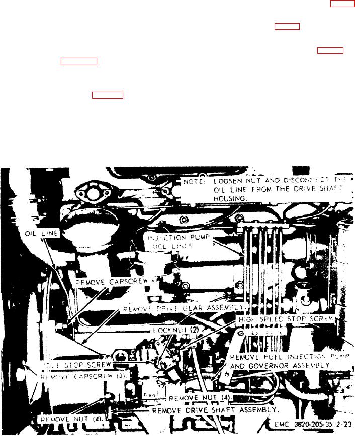
( 2 ) Refer to figure 19, and remove the fuel
i n j e c t i o n pump and governor assem-
67. Fuel Injection Pump and Governor
bly from the engine.
Assembly Cleaning, Inspection,
b. Disassembly. Refer to figure 20, and dis-
and Repair
assemble the fuel injection pump and governor
a. Cleaning. Clean all parts, except seals,
assembly.
gaskets, and preformed packing with a lint-
C a u t i o n : When disassembling the fuel injec-
f r e e cloth dampened in an approved cleaning
tion pump and governor assembly, keep all
solvent.
parts in a clean pan containing clean fuel oil to
Figure 19. Fuel injection pump and governor, drive shaft, and drive gear assemblies,
removal and installation.
52
AGO 8498A