
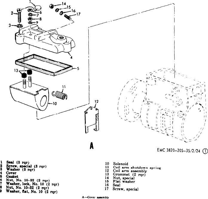
Figure 20. Fuel injection pump and governor assembly, exploded view.
b. Inspection and Repair.
thread damage, cracks, and distortion.
Replace all defective parts.
(1) Inspect all packing, seals, and gaskets
(3) Inspect the regulating plunger, rotor,
for distortion or damage, and all
plungers, distributor rotor, cam roll-
springs for wear, distortion, and
ers and shoes, governor weights, gov-
breakage. Carefully inspect all bores,
ernor linkage, and metering valve for
g r o o v e s , and seal seats for damage.
f r e e d o m of movement. If any parts
Replace any defective parts.
are sticking, but not visibly damaged,
( 2 ) Inspect each part of the injection
c l e a n the parts thoroughly with an
pump for wear, foreign material, rust,
a p p r o v e d cleaning solvent. Replace
nicks, chipping, s c r a t c h e s , scores,
any parts that do not move freely.
53
AGO 8498A