Note. When installing the body assembly (31, fig. 17)
60. Overspeed Governor Assembly
compress the retaining ring (22) and seat it in the
Reassembly and Installation.
groove in the body assembly.
a. Reassembly. Refer to figure 17, and reas-
b. Installation. Install the overspeed gov-
s e m b l e the overspeed governor in the reverse
e r n o r assembly (TM 5-3820-205-20/l).
order.
Note. When reassembling the governor fill the cavity
Section
VII.
FUEL
INJECTOR
ASSEMBLIES
62. Fuel Injector Assemblies Removal
61. General
and Disassembly
The fuel injector assemblies on the roll
a. Removal. Remove the fuel injector assem-
c r u s h e r engine have pintle-type nozzles. They
blies (TM 5-3820-205-20/l).
inject the fuel oil into the cylinders of the
d i e s e l engine at a high-pressure (1,750-1,850
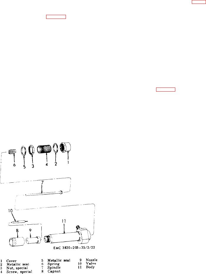
b . Disassembly. Refer to figure 18, and dis-
psi). The fuel injectors are held in the engine
assemble the fuel injector assembly.
b l o c k by a holddown yoke secured with studs
and nuts. There are two fuel lines attached to
t h e injector, one the high pressure line from
63. Fuel lniector Assemblies Cleaning,
t h e injection pump, and the other the excess
Inspection, and Repair
fuel return line to the pump.
a. Cleaning.
(1) Clean all carbon off the nozzle and
valve. Do not use sharp tools or abra-
sives.
(2) Clean the remaining parts of the fuel
injector in an approved cleaning sol-
vent.
C a u t i o n : Do not touch any polished
surface with the fingers after flushing.
Moisture from the fingers will cause
corrosion.
b. Inspection and Repair.
(1) I n s p e c t t h e s p i n d l e a n d s p r i n g f o r
damage or wear. A pitted or corroded
s p r i n g must be replaced. Replace all
defective parts.
( 2 ) Inspect the holder and be sure all pas-
sages are clean.
(3) Inspect all threaded parts of the fuel
injector for damage to threads. Re-
place all parts having defective
threads.
( 4 ) Inspect the metallic seals and gaskets
for wear and damage. Replace a worn
or damaged seal or gasket.
Figure 18. Fuel injector assembly, exploded view.
50
AGO 8498A

