
of drive pulley for wear and scoring.
b. lnstall the radiator assembly (par. 44).
Replace defective parts as necessary.
c. Install the fan belts (TM 5-3820-205-
84. Vibration Damper and Drive Pulley
20/l).
Installation
a . Refer to figure 26, and install the vibra-
tion damper and drive pulley on the engine.
S e c t i o n X I I I . T I M I N G GEAR AN D EN D PLAT E ASSEM B L Y
Se
that is attached to the camshaft. The drive
85. General
adapter gear meshes with the camshaft gear
The timing gear asssembly is located at the
and turns at half the speed of the engine crank-
front of the engine. The timing gear cover
shaft.
s e r v e s as a bearing for the front engine sup
86. Timing Gear and End Plate
port; as a cover for the timing gears, and also
Assembly Removal
holds the engine front oil seal. The timing gear
train consists of a helical drive pinion, mounted
a. Remove the engine housing (TM 5-3820-
on the crankshaft, which drives a helical gear
205-20/1).
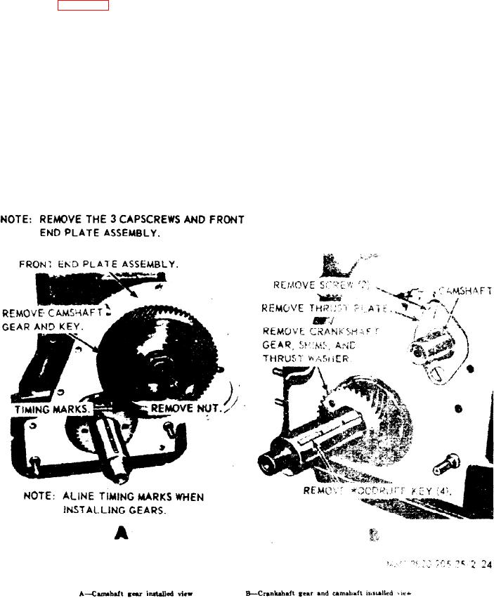
Figure 27. Timing gears and end plate assembly, removal and installation
AGO 8498A