
S e c t i o n X V . EN G I N E OI L PU M P ASSEM B L Y
Se
95. Engine Oil Pump Assembly Cleaning,
93. General
Inspection, and Repair
The engine oil pump assembly is a gear-type
a. Cleaning. Clean all parts of the oil pump
p u m p that is driven by the camshaft. The oil
i n an approved cleaning solvent. All gaskets
pump is located in the crankcase of the engine
removed must be discarded and replaced.
o n the center main bearing. The oil pressure
relief valve is an integral part of the oil pump
b. Inspection and Repair.
a n d may be adjusted through the access hole
(1) inspect the gears for correct clear-
i n the oil pan. Attached to the oil pump is a
a n c e . Clearance should be from 0.001
floating-type screen which filters the oil as it
t o 0.003 inch, and gears should not
is picked up by the oil pump.
contact the walls of the pump
chamber.
94. Engine Oil Pump Assembly Removal
(2) Inspect the cover and face of the gears
and Disassembly
f o r excessive wear or scoring. With
the gasket assembled to the body,
a. Removal.
t h e r e should be 0.0015 to 0.006 inch
(1) Remove the engine assembly (par.
c l e a r a n c e between the gears and the
29).
cover. Replace cover or gears if they
a r e worn or scored.
(2) Remove the engine housing (TM 5-
3820-205-20/l).
( 3 ) Inspect the pump body for cracks or
breaks. R e p l a c e a d e f e c t i v e p u m p
( 3 ) Remove the engine oil pan (par. 90).
body.
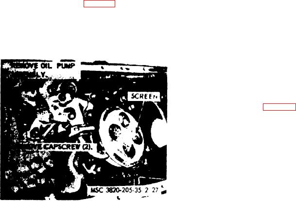
(4) Refer to figure 30, and remove the oil
(4) Inspect the drive shaft and shaft stud
p u m p assembly from the engine.
f o r wear and scoring. Replace a de-
fective shaft.
b. Disassembly. Refer to figure 31, and dis-
assemble the oil pump assembly.
(5) Inspect the relief valve piston for free-
d o m of motion and the valve spring
Note. The shaft (16). gears (17 and 18). and key
f o r proper pressure.
(19) are removed from the body (23) as an assembly,
and then the gear and key are removed from the shaft.
( 6 ) The oil pressure may be adjusted by
turning the adjustment screw. Engine
o i l pressure must be maintained be-
tween 55 and 65 psi.
96. Engine Oil Pump Assembly Reassembly
and Installation
a. Reassembly. Refer to figure 31, and re-
assemble the oil pump assembly in the reverse
order,
Note. Install the key (19) and gears (18 and 17) on
the shaft (16) and install as an assembly in the body
(23).
b . Installation.
( 1 ) Refer to figure 30, and install the oil
pump assembly on the engine.
( 2 ) I n s t a l l the engine oil pan (par. 92).
(3) Install the engine housing (TM 5-
3820-205-20/l).
Figure 3O. Engine oil pump assembly, removal and
( 4 ) I n s t a 1 1 the engine assembly (par. 29).
installation.
AGO 8498A