
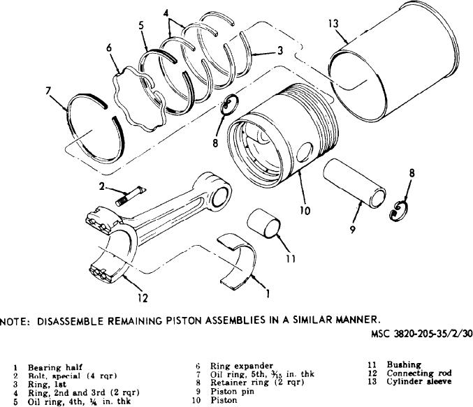
Figure 33. Piston, sleeve, and connecting rod assembly, exploded view.
f r o m 1.7503 to 1.7505 inch. Replace
(7) Install the piston rings in the respec-
connecting rod bushings that are worn
tive cylinder sleeve and check for
m o r e than 1.7515 inch in diameter.
p r o p e r ring gap with a feeIer gage.
T h e proper ring gap is from 0.018 to
( 1 0 ) Clamp the connecting rod and piston
0 . 0 3 2 inch. If the ring gap is smaller
a s s e m b l y without rings on the man-
than that specified, dress off the ends
drel with an alining fixture, and with
of the rings squarely with a file.
the connecting rod bearings in place.
Check the gap between the surface
( 8 ) Measure the piston pins with an out-
plate and the piston along the piston
s i d e micrometer for proper diameter
skirt, with the piston held at several
of 1.7500 to 1.7498 inch. Replace pis-
a n g l e s to the connecting rod. If the
ton pins with a diameter smaller than
gap is not the same at all angles, the
1.7495 inch.
connecting rod is twisted and must be
( 9 ) Inspect the connecting rod bushings
replaced.
for scoring, scratches, and other indi-
( 1 1 ) Hold the piston parallel to the con-
c a t i o n of wear and damage. Measure
necting rod and check the gap between
t h e i r diameter with a pair of inside
the piston skirt and the surface plate.
m i c r o m e t e r s . Proper measurement is
74
AGO 8498A