
Figure 35 --Continued.
Section
XIX.
MAIN
BEARINGS
AND
CRANKSHAFT
109. General
110. Main Bearings and Crankshaft
Removal and Disassembly
The crankshaft is supported by seven main
bearings. The end and center main bearings
a. Removal.
are different, whereas the four intermediate
(1) R e m o v e t i m i n g g e a r s a n d f r o n t e n d
main bearings are alike. The front main bear-
p l a t e (par. 86).
i n g is polished on one side to back up a brass
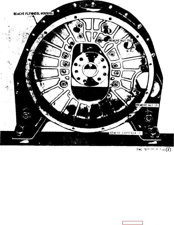
( 2 ) R e m o v e flywheel housing (par. 106).
thrust ring, which is instahed between the
(3) R e m o v e connecting rod bearing caps
f r o n t main bearing and the first throw of the
( p a r . 98).
crankshaft. Dowel pins in the block locate the
bearing caps accurately to the block. The jour-
(4) Refer to figure 36, and remove the
n a l s of the crankshaft are hardened to resist
main bearings and crankshaft from
wear and scoring.
the engine.
AGO 8498A