
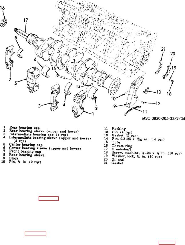
Figure 37. Main bearings and crankshaft, exploded view.
(4) Install timing gears and front end
112. Main Bearings and Crankshaft
p l a t e (par. 88).
Reassembly and Installation
Note. Check crankshaft end play before
a. Reassembly. Refer to figure 37, and reas-
installing front end plate.
semble the main bearings and crankshaft in the
r e v e r s e order.
c. Checking Crankshaft End Play. A shim
Note. Install the bearing sleeves (2, 4, 6, and 8) in
p a c k containing shims of 0.002 inch and 0.008
the bearing caps and the engine block.
inch thickness is incorporated in the assembly
between the front end of the main bearing
b. Installation.
journal and the crank gear. By removing or
(1) Refer to figure 36, and install the main
adding shims, this end play can be corrected to
bearings and crankshaft on the engine.
fall within the specifications (table 2).
(2) Install connecting rod bearing caps
Note. At all times, when checking end play, the
( p a r . 100).
crank gear must be tightened firmly against the shim
(3) Install flywheel housing (par. 108).
pack.
AGO 8498A
81