
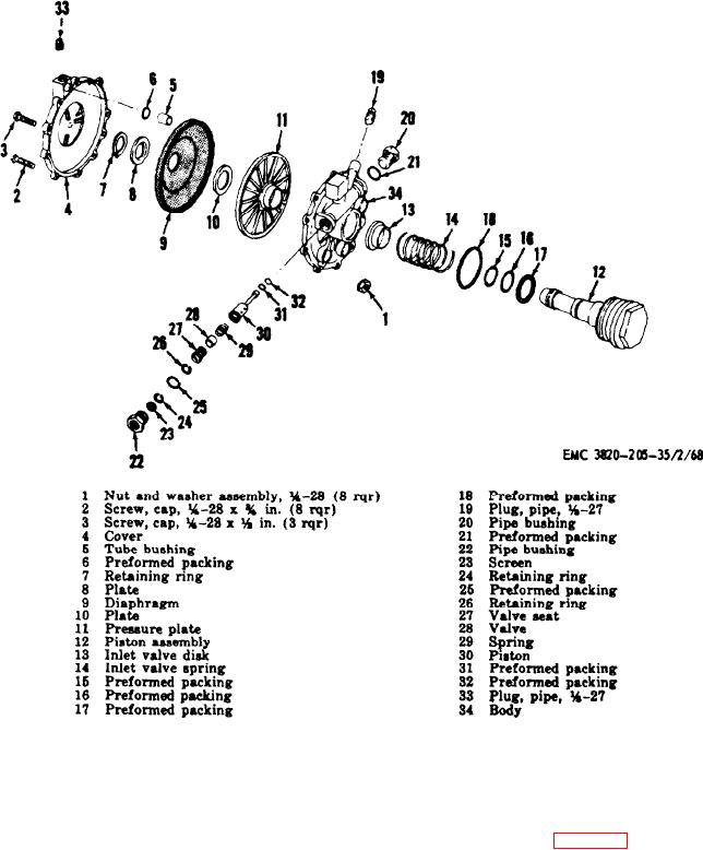
Figure 65. Air relay valve assembly, exploded view.
2 3 3 . Air Chamber Assembly Reassembly
232. Air Chamber Assembly Cleaning,
a n d Installation
Inspection, and Repair
a . Reassembly. Refer to figure 66, and reas-
a. Cleaning. Clean all parts with an ap-
semble the air brake chamber assembly in the
proved cleaning solvent and dry thoroughly.
r e v e r s e order.
b . I n s p e c t i o n a n d R e p a i r . Inspect all parts
b. Installation. Install the air brake chamber
for wear and damage. Replace or repair worn
a s s e m b l y (TM 5-3820-205-20/1).
o r damaged parts.
AGO 8498A
135