
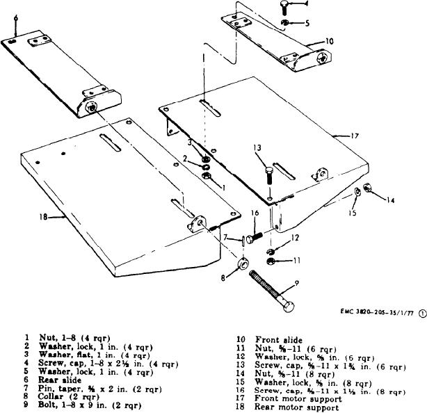
Figure 68. Main frame assembly, exploded view.
r e e l s and brackets (TM 5-3820-205-
(8) Install the air tank, relay valve, air
20/1).
f i l t e r s , connectors, airlines, and fit-
tings (TM 5-3820-205-20/1).
( 1 3 ) Install the leveling jacks (TM 5-3820-
205-20/1).
( 9 ) Install the toolbox and brackets (TM
5-3820-205-20/1).
(14) Install the fuel tank and brackets
(TM 5-3820-205-20/1).
(10) Install the ladders and walkways (TM
5-3820-205-20/1).
( 1 5 ) Install the battery box (TM 5-3820-
205-20/1).
( 1 1 ) Install the fire extinguisher bracket
(TM 5-3820-205-20/1).
(16) Install the tail, blackout, and clearance
lights (TM 5-3820-205-20/1).
(12) Install the power and feeder cable
AGO 8498A
139