
26. Hydraulic Cylinder Fails to Operate
Probable cause
Possible remedy
Leaking hydraulic lines................................................................Repair or replace hydraulic lines (pars. 133-135).
Seals or packing rings defective .................................................Replace seals and packing (pars. 133-135).
Hydraulic cylinder damaged .......................................................Repair or replace cylinder (pars. 133-135).
27. Jaw Crusher Fails to Operate
Probable cause
Possible remedy
Toggle plate broken ...................................................................Replace toggle plate (pars. 161-163).
Adjusting screws sheared or stripped ..........................................Replace adjusting screws (pars. 165-167).
28. Airbrakes Fail to Operate
Probable cause
Possible remedy
Air relay valve defective .............................................................Repair or replace air relay valve (pars. 200-202).
Air chambers defective ..............................................................Repair or replace air chambers (pars. 203-205).
Section III. REMOVAL AND INSTALLATION OF MAJOR COMPONENTS
OR AUXILIARIES
29. General
This section provides the necessary information to field
and depot maintenance personnel for the removal and
installation of the engine, pan feeder, scalper vibrating
screen, crusher, discharge conveyor, and the. bogie and
rear axle assemblies.
These assemblies may be
removed as an assembly for replacement or for major
repair to the Eagle Jaw Crusher Model 5157.
30. Engine Assembly
a.
Removal.
(1)
Loosen the tension on the drive belts
on the engine sheaves and remove
the belts (TM 5-3820-205-20/2).
(2)
Disconnect the battery lead from the
engine (TM 5-3820-205-20/2).
(3)
Disconnect the fuel supply lines from
the engine (TM 53820-205-20/2).
(4)
Remove the drive belt guards (TM 5-
382205-20/2).
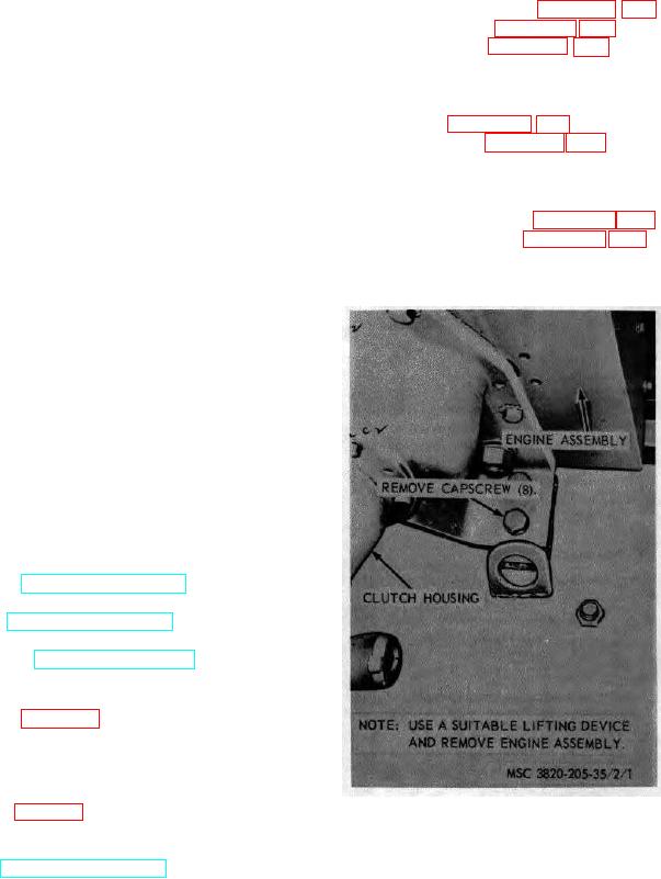
(5)
Refer to figure 1 and remove the
engine.
b.
Installation.
(1)
Refer to figure 1 and install the engine
Figure 1. Engine assembly, removal and installation
on the unit.
(2)
Connect the fuel supply line to the
engine TM 5-3820-205-20/2).
AGO 8456A
17