
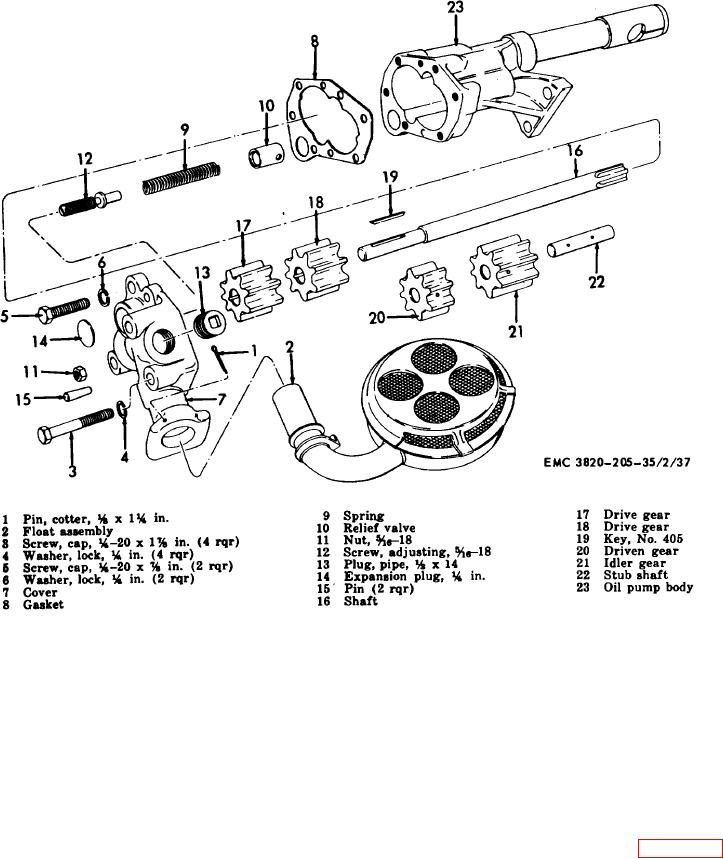
Figure 28. Engine oil pump assembly, exploded view.
should not contact the walls of the
(5)
Inspect the relief valve piston for
pump chamber.
freedom of motion and the valve
spring for proper pressure.
(2)
Inspect the cover and face of the
gears for excessive wear or. scoring.
(6)
The oil pressure may be adjusted by
With the gasket assembled to the
turning the adjustment screw. Engine
body, there should be 0.0015 to 0.006
oil pressure must be maintained
in. clearance between the gears and
between 55 and 65 psi.
the cover. Replace cover or gears if
95.
Engine Oil Pump Assembly Reassembly and
they are worn or scored.
Installation
(3)
Inspect the pump body for cracks or
Reassembly.
Refer to figure 28 and
a.
breaks. Replace a defective pump
reassemble the engine oil pump in the reverse order.
body.
Note. Install the key (19) and the
(4)
Inspect the drive shaft and shaft stud
gears (18 and 17) on the shaft (16)
for wear and scoring. Replace a
and install as an assembly in the
defective shaft.
body (23).
AGO 3456A
61