
(2)
Install the engine oil pan (par. 91).
b.
Installation.
(3)
Install the engine housing (TM 5-
(1)
Refer to figure 27 and install the
3820-205-20/2).
engine oil pump assembly on the
engine.
(4)
Install the engine assembly (par. 30).
Section XVI. PISTON AND CONNECTING ROD ASSEMBLIES
(3)
Remove the cylinder head and valves
96.
General
The pistons used in this engine are made of an
(4)
Remove the oil pump assembly (par.
aluminum alloy. There are three compression rings and
two oil rings on each piston. A piston pin connects the
piston to the connecting rod. Each connecting rod and
(5)
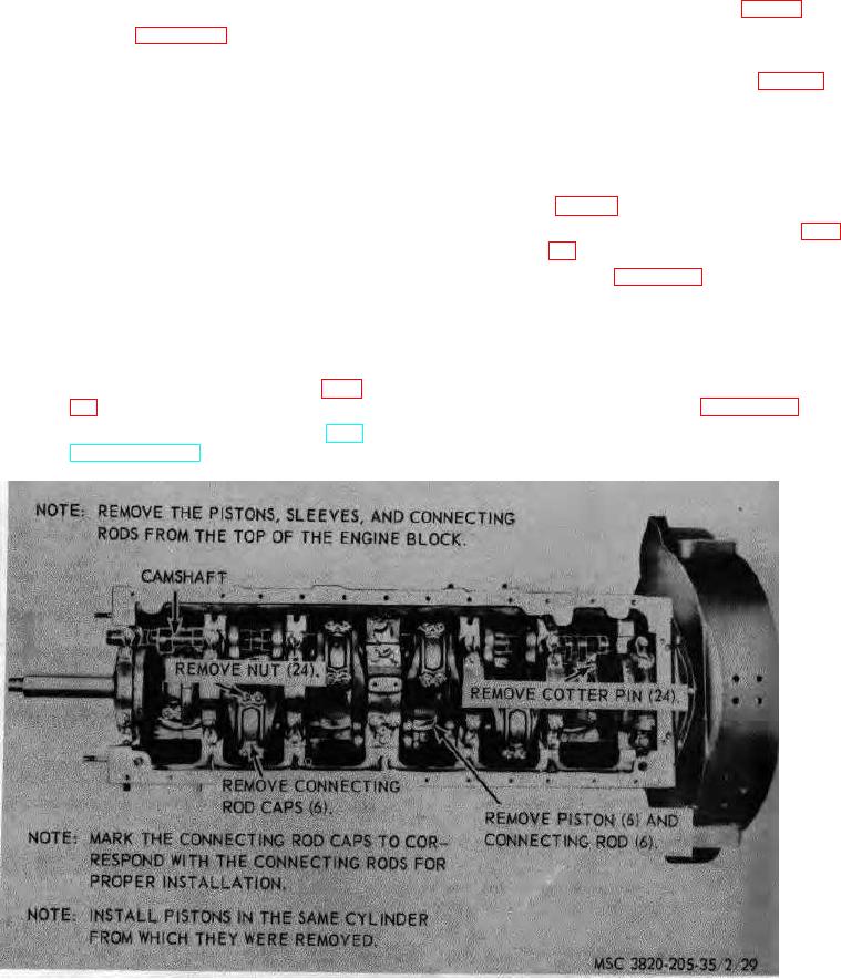
Refer to figure 29 and remove the
rod cap are matched and are not interchangeable.
piston and connecting rod assemblies
from the engine.
97.
Piston and Connecting
Rod
Assemblies
Removal and Disassembly
Note. Remove the ridge and carbon from the top of
the cylinder sleeve before removing the piston from
a.
Removal.
the engine block.
(1)
Remove the engine assembly (par.
Disassembly..
Refer to figure 30 and
b.
disassemble the piston and connecting rod assemblies.
(2)
Remove the engine housing (TM
Figure 29. Pistons, sleeves, and connecting rod assemblies, removal and installation.
AGO 3456A
62